Blog

Compare Physical Interface and Cabling Types CCNA

Physical interface and cabling types is another topic from the current CCNA exam blueprint. Network engineers must know what the physical connectivity options exist, understand their limitations in speed and bandwidth. Power over Ethernet (PoE) is another related and important topic, as many critical devices are now dependent on network-delivered power. Network vendors and IEEE work to identify and standardize new ways to support higher power demands.

CCNA Exam test knowledge of these topics:

1.3 Compare physical interface and cabling types

1.3.a Single-mode fiber, multimode fiber, copper

1.3.b Connections (Ethernet shared media and point-to-point)

1.3.c Concepts of PoE

This first section is dedicated to types of physical interfaces available in Cisco LAN switches. The further sections present cabling and POE details.

Physical Interfaces

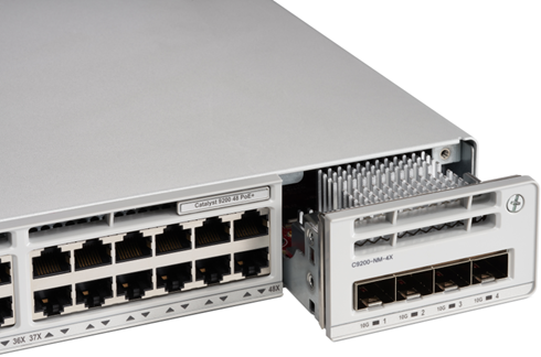
Cisco network devices can have either fixed ports or hot-pluggable transceivers slots. Figure 1 shows a Cisco Catalyst 9200 switch with 48x 10/100/1000 copper POE-enabled ports and an extension module, C9200-NM-4X which provides 4x SFP/SFP+ slots (on the right).

Cisco Catalyst 9200 switch with 4x 10GE SFP module
Figure 1. Cisco Catalyst 9200 switch with 4x 10GE SFP module
Courtesy of Cisco Systems, Inc. Unauthorized use not permitted

Different types of transceivers can be inserted into an SFP slot. For example, C9200-NM-4X module shown in Figure 1, can accept 1Gbps SFP modules and 10Gbps SFP+ modules. Figure 2 below shows SFP modules on the left and direct-attach Twinax copper cable on the right. This cable combines 2 connected SFPs and is a cost-effective way to connect devices in the same or adjacent racks.

SFPs and Direct-Attach Twinax Cables
Figure 2. SFPs and Direct-Attach Twinax Cables
Courtesy of Cisco Systems, Inc. Unauthorized use not permitted

Modern Catalyst switches, such as Catalyst 9000 series, have 2 types of copper interfaces:

  • 10/100/1000Mbps
  • Multigigabit with speed up to 10Gbps

Both types of interfaces support several standards and can negotiate different speeds with the connected device. For example, 10/100/1000 copper ports of Catalyst 9200 switch shown in Figure 1 support 10Base-T, 100-BaseTX and 1000Base-T. Multi-gigabit ports can negotiate 100Mbps, 1Gbps, 2.5Gbps, 5Gbps, and 10Gbps.

802.3 Standards

IEEE 802.3 family of standards defines physical interface specifications for the wired Ethernet. The table below shows some of the 802.3 standards.

StandardSpecificationPhysical Media
802.310Base-TUTP Cat 3 or higher
802.3u100Base-TXUTP Cat 5 or higher
802.3ab1000Base-TUTP Cat 5 or higher
802.3z*1G over fiberDifferent types of fiber
802.3bzMultirate 2.5G/5GUTP Cat 5E or higher
802.3an10G Base-TUTP Cat 6 (55m), Cat 6A
802.3ae**10G over fiberDifferent types of fiber
802.3by25GbpsDifferent types of fiber, twinax
802.3ba40Gbps/100GbpsDifferent types of fiber, twinax

Table 1. 802.3 Standards, Speed and Physical Media

*802.3z standard is called Ethernet over Fiber-Optic at 1Gbit/s and references multiple other standards. The example of commonly used options are 1000Base-SX (multi-mode fiber) and 1000Base-LX (multi-mode/single-mode fiber). Check this Wikipedia article for the full list.

**Has references to multiple standards depending on fiber type. The most commonly used options are 10GBase-SR, 10GBase-LR. Check this Wikipedia article for the full list.

Small Form-factor Pluggable Transceivers (SFPs)

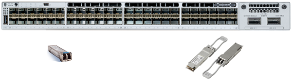
SFPs are network interface modules. Their specifications are developed and maintained by industry vendors group, i.e. not by IEEE. While the modules manufactured by different companies should be compatible, many vendors, including Cisco, support only their own branded SFPs. QSFP has a larger size and the picture below shows the difference between SFPs and QSFPs modules, as well as switch-side sockets. In this example, it is a Catalyst 9300 48-SFP+ port switch with a C9300-NM-2Q network module (accepting 2x QSFP+ modules).

Catalyst 9300 with SFPs (on the left) and QSFPs (on the right)
Figure 3. Catalyst 9300 with SFPs (on the left) and QSFPs (on the right)
Courtesy of Cisco Systems, Inc. Unauthorized use not permitted

The table below lists different types of SFPs along with the supported speed. To confirm if a specific module can be used in a specific Cisco device use the transceiver compatibility tool available here.

NameSpeed
SFP1 Gbps
SFP+10 Gbps
SFP2825 Gbps
QSFP40 Gbps
QSFP2840/100 Gbps
QSFP-DD100/400 Gbps

Table 2. SFPs and Speed

Unshielded Twisted Pair

Copper connectivity is based on Unshielded Twisted Pair (UTP) cabling of different categories. A higher category number refers to the newer standard and better parameters. An Ethernet cable consists of 8 wires, which are twisted together in pairs. The maximum distance for copper cabling is 100m. The connector is called 8P8C and also commonly referred to as RJ45.  There are 2 standards defining how individual wires are terminated within the connector – T568A and T568B. Refer to Wikipedia article for further information on pin-outs.

End devices have MDI (Medium Dependent Interfaces) ports and switches have MDI-X ports. -X means that the receive and transmit pairs are switched. To connect MDI to MDI-X straight-through cable is used. This cable has connectors with the same pin-out scheme used on both sides – either T568A or T568B. To connect MDI to MDI (host to host back-to-back), or MDI-X to MDI-X (switch to switch) crossover cable is required. A crossover cable has a connector with T568A pin-out on one side and T568B pin-out on another side.

Many modern switches can automatically switch their ports between MDI-X and MDI. They can use straight-through cables to connect to each other and don’t require a crossover cable.

Optical Fiber

Optical fiber cabling is usually more expensive to install, however, it has many benefits when compared to copper. In most cases, fiber cables can provide higher bandwidth over greater distances.

Fiber cabling is divided into 2 types:

  • Multi-mode with categories of cables OM1, OM2, OM3, OM4 and OM5
  • Single-mode of two types – OS1 and OS2

A fiber cable has a core and cladding around it. Multi-mode cable’s core is either 50 or 62.5 micrometers in diameter with 125 micrometers cladding. For comparison, human hair has a diameter between 20-40 micrometers. Single-mode cable’s core is thinner – between 8 and 10.5 micrometers in diameter with the same size 125 micrometers cladding. Multi-mode transmitters use a wavelength of 850nm and 1300nm; single-mode is 1310 or 1550 nm based. Cisco publishes information for each SFP on maximum supported distance based on cabling characteristics. These datasheets can be accessed via the Cisco transceiver compatibility tool. A very detailed comparison table of multimode cables is available here.

Single-mode cabling can cover much greater distances than multi-mode cables. See “Modal dispersion” article on Wikipedia explaining physics behind this.

Multimode OM numbers, as UTP categories, are better with larger number and provide better speed and distance. Single-mode OS1 is for indoor use/shorter distances and OS2 is for outdoor/long distance-use.

Connectors

Cisco fiber SFPs and some QSFPs have a duplex LC connector. Some QSFPs can also have MPO connectors. Check this article on Wikipedia with photos and specifications of different types of connectors.

Power Over Ethernet (POE)

Cisco Catalyst switches perform role of Power Sourcing Equipment (PSE). Cisco IP Phones, Access Points and other end devices are Powered Devices (PDs). Standards and data sheets usually list 2 power values: 

  • delivered on the switch port (PSE)
  • received at the end device (PD)

The value at PD is always smaller than at PSE due to the power dissipation in cabling.

Standards

Cisco introduced its proprietary technology before IEEE standardized the POE. Cisco inline power can provide up to 10W at the PSE. Switch sends a fast link pulse to detect power enabled device, which then sends a link pulse back. The switch and device negotiate the final power level via Layer 2 capability exchange protocol – Cisco Discovery Protocol (CDP). Original Cisco inline power switches and end devices reached their End-Of-Support dates a long time ago and are replaced with newer platforms using POE standards described below.

In 2003 IEEE released the first POE standard – 802.3af. The standard isn’t compatible with Cisco’s proprietary implementation. PSE can deliver a maximum of 15.40W with available power at PD of 12.95W. This specification defined PD detection and classification mechanisms using electrical signaling. PD has an option to signal to the switch which class it belongs to. With this information, the switch knows how much power it should deliver. As table 3 shows, 802.3af defined 3 classes and class 0, which means that no classification is supported.

Power (PSE side)SpecificationClass
4WIEEE 802.3af Type 1Class 1
7WIEEE 802.3af Type 1Class 2
10WCisco inline-power
15.4WIEEE 802.3af Type 1Class 3
15.4WIEEE 802.3af Type 1Class 0 (not classified)
30WIEEE 802.3at Type 2Class 4
45WIEEE 802.3bt Type 3Class 5
60WIEEE 802.3bt Type 3Class 6
60WCisco UPOE
75WIEEE 802.3bt Type 4Class 7
90WIEEE 802.3bt Type 4Class 8
90WCisco UPOE+

Table 3. POE Wattage and Associated Standards

In 2009 IEEE released the new 802.3at standard. Devices supporting it were called Type 2 or POE+. PSEs and PDs complying with earlier 802.3af standard were labeled as Type 1 devices. 802.3at provides up to 30W/25.50W of power. Power levels of 30W and higher have additional stage negotiations using either electrical signals or layer 2 capability exchange protocols, such as LLDP and CDP.

Standard is backward compatible and supports 802.3af Class 1-3 devices. New Class 4 is allocated for 30W devices. 802.3at is widely used. Current generation of access switches, such as Catalyst 9200, and modern access points supporting it. Both 802.3af and 802.3at use only 2 pairs of wires in 4-pair UTP cable to provide power.

New use cases emerged, for example, smart buildings with POE-enabled lighting and network-powered display screens. These devices demanded more power. In 2011, Cisco introduced proprietary Universal Power over Ethernet (UPOE) technology to support up to 60W with the use of all 4 pairs in UTP cable. IEEE released 802.3bt standard in 2018 with up to 90W of power at PSE. The standard introduced Type 3 devices (60W) and Type 4 devices (90W). IEEE standard also made use of all 4.

Cisco UPOE and IEEE 802.bt Type 3 both deliver 60W but operate differently. Cisco publishes a list of UPOE Catalyst switches and line cards that comply with 802.3bt. Cisco proprietary UPOE+ was released to support 90W. UPOE+ switch modules can support 802.3bt Type 4 devices.

Some switches and line cards from Catalyst 9300 and 9400 families support UPOE and UPOE+. Catalyst 9200 switches support only POE+ (802.3at).

Self-test Questions

What are the 2 types of copper ports Catalyst 9000 series switches support?
• 10/100/1000Mbps

• Multigigabit – 100Mbps and 1/2.5/5/10Gbps
What are 2 types of fiber cabling?
• Multi-mode (OM1, OM2, OM3, OM4 and OM5)

• Single-mode (OS1 and OS2)
What are 2 roles a device can perform in POE configuration?
• Power Sourcing Equipment (PSE) – the switch providing power

• Powered Devices (PDs) – end device consuming power

Cisco DNA Center

This article describes the role and functions of Cisco DNA Center in the context of CCNA exam blueprint requirements.

Relevant CCNA exam topics are available here:

  • Explain the role and function of network components: Controllers (Cisco DNA Center and WLC*)
  • Compare traditional campus device management with Cisco DNA Center enabled device management

* Wireless LAN Controllers functions were discussed in the blog post dedicated to wireless devices, however, this article will use WLCs along with other types of controllers for comparison.

DNA Center Overview

Cisco DNA Center is a management software and a controller for SD-Access. At the time of the writing, it is available only as a hardware appliance. DNA Center is positioned in Cisco’s product line as the replacement for Cisco APIC-EM. It can also replace Cisco Prime Infrastructure.

There are 3 available options of hardware appliances to choose from:

  • DN2-HW-APL (C220 M5, 44 cores) – up to 1000 devices
  • DN2-HW-APL-L (C220 M5, 56 cores) – up to 2000 devices
  • DN2-HW-APL-XL (C480 M5, 112 cores) – up to 5000 devices

Cisco supports a single node deployment or a cluster of 3 appliances for high availability.

DNA Center can operate with 2 types of networks:

  • Traditional campus networks
  • SD-Access fabric

Traditional Networks

DNA Center can work with non-SD-Access networks similar to traditional network management software. Policy-driven automation is available in this mode, but it is optional. Assurance and analytics functionality can be opened with even only read-only access to the network and provide a safe way to get familiar and to evaluate DNA Center’s features.

SD-Access Fabric

Cisco introduced a new paradigm for medium- to large- size enterprise networks called intent-based networking. In this architecture, an administrator communicates intent to the controller or requesting “what” he wants to achieve. He doesn’t need to specify device-specific instructions (“how?”) for the changes to be applied. A controller accepts instructions from an administrator via GUI or from an application via API and then applies configuration to the devices it controls.

Software-Defined Access or SD-Access is an implementation of this paradigm. We’ve published an article called SD-Access Components and it explains functions of DNA Center only briefly; this blog post is expanding its coverage. SD-Access has multiple underlying protocols to provide scalable and flexible, but relatively complex virtualized network infrastructure. DNA Center is the key that hides the complexity by providing a level of abstraction that allows network operators to focus their attention on more high-level configuration concepts, such as policies.

Role in the network

In SD-Access fabric, DNA Center plays a more essential role compared to one in the non-SDA network. With SD-Access fabric, while the underlay network can be built manually, the overlay networks are created and operated via DNA Center. In the traditional network, an administrator can decide which tasks should be performed by DNA Center and which ones are to be done directly on the device.

DNA Center has ability to perform many tasks in the network lifecycle:

  • Day 0. Onboarding and discovery. During this stage DNA Center can be used for zero-touch provisioning (ZTP) with Plug and Play (PnP) protocol
  • Day 1. Provisioning. Policy-based templates can be defined and applied to multiple devices grouped into a hierarchy of sites
  • Day 2, N. Operation via policy configuration, monitoring, troubleshooting, and software patching. DNA Center has multiple features simplifying network operations tasks, including, Software and Image Management, zero-touch RMA

Controller operations

Management plane

A network controller can use many protocols to interact with the network devices and this communication is referred to as Southbound connectivity. DNA Center can use multiple management protocols, for example, CLI, Netconf or SNMP. To provide some comparison with other controllers – Cisco SD-WAN uses Netconf to push configuration from vManage to vEdge devices and Cisco WLC uses CAPWAP protocol to communicate with access points.

End devices, such as switches and routers run normal IOS-XE software. Their configuration mode can be accessed locally and changes pushed from DNA Center can be observed via a device’s configuration files.

Control plane

Cisco DNA Center in both modes of operations is distributed across switches, access points and routers. It keeps the network devices in charge of their control plane operation. The network will continue to function if the DNA Center appliance is not reachable. For example, it doesn’t participate in dynamic route propagation or reflection, as vSmarts in SD-WAN.

Data plane

Cisco DNA Center doesn’t perform transit data forwarding functions. In comparison, Cisco Wireless LAN Controller can switch traffic in certain deployment modes.

Features and Functions

DNA Center functions and features can be divided into 4 groups, as shown in Figure 1.

Figure 1. DNA Center Features and Functions

Automation

This group of features is responsible for performing operational and provisioning tasks without applying the configuration manually to the devices. Some of the examples are available below.

Network Design and Profiles

Logical separation of the network into a hierarchy of regions and sites. The profiles, which include common parameters, such as DNS, DHCP server details, are then associated with this logical containers, so all sites under them inherit the settings.

Software Image Management (SWIM)

This feature ensures that consistent software image versions are deployed to devices in the network. DNA Center performs checks prior and post-installation. For example, free space on the flash memory is one of such checks.

Network Plug and Play (PnP)

A very useful feature when the number of deployed devices is high. A device just needs to be plugged in and receive an IP address to receive its configuration automatically. To locate DNA Center several discovery methods are supported, such as using a DHCP option and a DNS name.

QoS Configuration Automation

One of the challenging aspects of the day-to-day operation of the network is QoS policy implementation. Applications on the network can change or new ones are added. If the network is managed manually, keeping configuration up-to-date with properly classified traffic and its preferred treatment can consume a lot of time. Different hardware QoS implementation on different models of devices further increases the complexity.

DNA Center provides an intuitive user interface that allows the administrator to select one of the pre-defined application templates and to choose if its business-relevant or not. Then scope, or which devices should have this policy, is selected and configuration is applied to the network.

Assurance

Another function of a controller is to provide centralized monitoring. DNA Center component responsible for it is called DNA Assurance. It provides many unique features, such as the correlation of different types of information; focused 360 views for the network devices and clients; and retrospective view with Network time travel feature.

Dashboards

There are multiple dashboards available each focusing on different aspects of network health. Performance of business-relevant applications, clients and network devices is monitored and top issues are displayed.

Device 360, Client 360 and Network Time Travel

These features provide a device-centric view of a device or a client. It provides an administrator with ability to quickly access relevant to an endpoint or device information and its health score. For example, it simplifies troubleshooting when a user complains about application performance. By using the search function to quickly locate the user and his device, an administrator can identify if there are issues with the network reachability, such as poor RF signal or packet drops.

It also usually takes some time after an issue occurs and before an administrator starts working on the ticket. By that time, an alert can be cleared out making troubleshooting more difficult. Network Time Travel allows focusing the device view on a specific time in the past (up to 14 days) to see events and alerts that were active at that time.

Path Trace

Path Trace visually displays every device in the path between two IP addresses across the network. It can optionally include information about devices that can be blocking the traffic with access lists, as well as interface and QoS (Quality of Service) statistics.

AI Network Analytics

Analytics powered by Artificial Intelligence/Machine Learning algorithms helps to proactively identify issues. First, the network-specific baseline is gathered and learning occurs. This information is then used to evaluate anomalies to alert the administrator of a possible issue.

SD-Access

This group of functions is specific to SD-Access. Includes functions required to perform the SD-Access controller’s management features for fabric infrastructure and fabric wireless.

Fabric Assurance

DNA Center provides additional monitoring features for fabric, such as the correlation of fabric’s underlay and overlay, reachability between fabric edge, control and border nodes.

Group-based Policy Configuration

DNA Center integrates with Cisco ISE (Identity Service Engine) to enable the use of identity-based policies using Cisco TrustSec. Group-based Policy configuration allows an administrator to configure group and policy management from the user interface of the DNA Center, which then communicates with ISE and fabric.

The main purpose of this feature is to let network devices to infer user identity without relying on IP address or VLAN information mapping. For example, when a user or a device is authenticated with ISE, traffic from this device is marked with a special tag called SGT (Security/Scalable Group Tag). SD-Access places this tag into VXLAN header, so other devices can tell which user or group this datagram belongs to and use this information to apply security and QoS policies.

Platform

In the management plane section, we introduced the concept of Southbound protocols in Software Defined Networks, i.e. from the controller to end devices, such as switches and routers. Northbound protocols, as their name suggests are working in the opposite direction, and are responsible for communication from external services to the controller for 3rd party integration. Cisco DNA Center supports REST (Representational State Transfer) APIs for such integration.

Integration with Service Management Platforms

Cisco DNA Center can be integrated via API with Service Management Platforms. This integration provides the ability to interact with platforms such as ServiceNow. For example, the Software Imaging feature of the DNA Center can log a change request in ServiceNow and perform image push only once it is approved. Another use case can be automated ticket logging when DNA Center discovers an issue.

IPAM Integration

IP Address management provides centralized management of IP pool allocation. Integrating with such a system allows DNA Center to reserve pools for workflows.

Self-test questions

What are 2 types of networks that DNA Center can work with?
• Traditional networks as a management platform

• SD-Access fabric as a controller and a management platform
DNA Center supports Southbound and Northbound protocols. What are they?
• Southbound protocols are responsible for communication from a controller to managed devices

• Northbound protocols or APIs provide access to the controller from external systems

Explain Role and Function of Network Components – Part 3 – Routers, Firewalls, and IPSs

This is the third article about the roles and functions of different network components (clock on the links for the first and second parts). In this part we will discuss operations of devices deployed on the network edge – Routers, Firewalls and Intrusion Protection Systems (IPSs).

Network edge provides connectivity between the company’s branch offices, data centers, remote workers, business partners, and the Internet. These devices must support a variety of transport technologies and provide security services.

There are two main types of edge connectivity:

  • Internet
  • WAN

Internet connectivity due to its public nature needs higher security control and devices such as firewalls, IPSs are usually deployed to enable the perimeter protection. Wide Area Network (WAN) in many environments was traditionally considered as a trusted network with only routers installed at the edge of each campus and branch.

In general, WAN links are more expensive and may not be available at every location. WAN connectivity is usually backed by agreed service level contracts and has guaranteed bandwidth and predictable latency. On the other hand, Internet links are cheap and offer more bandwidth, but no end-to-end service performance guarantees.

VPN tunneling over the Internet is used as a backup WAN connectivity method in many networks. Newer technologies, such as Cisco SD-WAN often use several Internet connections – as primary and backup WAN transport. SD-WAN routers can actively monitor links performance end-to-end and re-route traffic automatically based on the configured policy.

With these trends, the dividing line between WAN and Internet becomes less clear. Implementing security services on SD-WAN routers or installing firewalls behind it can be a reasonable choice.

Routers

The main function of a router is to perform Layer 3 forwarding or in most networks route IP (or IPv6) packets. Routers can run dynamic routing protocols to find the best paths to remote networks.

As we discussed in part 1 of this series, a Layer 3 Switch performs a similar function.

What is the difference between a Layer 3 switch and a router?

Historically, switches performed only Layer 2 functions and routers were responsible for Layer 3 operations. Topologies, such as router on a stick for inter-VLAN routing, were often deployed. Figure 1 displays a sample network demonstrating how the traffic between VLAN 10 and VLAN 20 hairpins via a router.

Figure 1. Router on a stick

With the introduction of Layer 3 functionality in switches, inter-VLAN routing functionality was moved to them from routers. The term Layer 3 switching is used to describe fast, hardware-accelerated routing.

For example, aggregation-level router, such as Cisco ASR 1002-HX has a performance of up to 78Mpps, which is outperformed by the entry-level Catalyst C9200-24PXG access switch capable of switching up to 262 Mpps (million packets per second).

There is a balance between flexibility and performance. Routers are capable of providing more services and this is the reason they have lower layer 3 processing performance numbers. For example, routers support many types of WAN links (such as DSL variations and 4G LTE), can accept full Internet routing table, provide advanced QoS capability and application awareness, perform firewall zone-based services, establish VPN tunnels, act as voice gateways and many other features.

Cisco website has a tool called Feature Navigator that allows us to look up a feature that a specific platform or software version provides.

Cisco router product portfolio

Cisco routers can be grouped based on the type of location where they are typically deployed:

  • Branch routers: ISR 900, ISR 1000, ISR 4000, Meraki MX
  • WAN aggregation: ASR 1000, NCS 5000/5500
  • Datacenter and clouds: CSR 1000v, Meraki vMX100
  • Service provider routers: ASR 1000, ASR 9000, Cisco 8000 Series

Cisco router software

Previously, all enterprise Cisco routers were running the Cisco IOS software. It is now mostly replaced by IOS-XE. ISR 900 models are the only devices in the current product line that use IOS.

IOS-XE is IOS’s successor and the majority of enterprise-level devices, including ISR 1000, ISR 4000, ASR 1000 and CSR 1000v, are running it. IOS-XE is based on Linux kernel with IOS being a process called IOSd. IOS-XE and IOS share command-line syntax.

Enterprise platforms running IOS-XE can also run the SD-WAN version of the software, which allows the router to be managed by SD-WAN controllers (more information about SD-WAN platforms is available here).

Service provider routers, such as NCS 5000/5500 and ASR 9000 are running IOS XR software.

Self-test question: What are the functions of a router?
• Layer 3 (in most cases IP or IPv6) traffic forwarding
• Maintains remote network reachability information via static configuration or dynamic exchange with other routers
• Supports a wide variety of interfaces, such as Ethernet, DSL, and LTE
• Has application visibility and ability to apply granular Quality of Service policies
• Provides different services, such as VPN, firewall and VoIP services

Firewalls and Intrusion Protection Systems (IPSs)

Let’s start this section by describing the logical functions of a firewall and an intrusion protection system.

Cisco firewall and IPS functions

A firewall evaluates traffic against configured ruleset and then allows or blocks it. A stateful firewall keeps track of allowed connections and can recognize return traffic, i.e. being part of an existing session, so it can be allowed too.

An Intrusion Protection System performs the security policy enforcement on transit traffic by either comparing its content to a set of patterns or by analyzing its behavior. These pre-defined patterns are called signatures and must be regularly updated.

Traditional firewalls and IPSs

Cisco product line used to have two different types of devices – one performing the firewall functions and another one was responsible for intrusion protection. Cisco PIX and its successor ASA (and routers with security feature set enabled) were performing traditional stateful firewall functions. They had some a limited IPS feature set too. However, for the full IDS/IPS functionality, Cisco IPS appliances and hardware modules were required. After SourceFire acquisition, its standalone IPS products were also added to Cisco’s product line.

Cisco provided integration options, however, they were based on two separately managed systems running in parallel. For example, ASA could accept an expansion module providing IPS functionality connected via ASA’s backplane. Later, hardware modules were replaced by virtual software processes using ASA as a host.

Next-Generation firewalls

Many security vendors took an approach of closely integrating both types of features in a single device, which became known as a Next-Generation Firewall (NGFW). Cisco also released a unified software platform that inherited ASA code as a stateful firewall engine and Snort IPS as intrusion protection system. This software is running on the current NGFW platforms and is called Firepower Threat Detection (or FTD).

In addition to stateful firewall and IPS functions, Next-generation firewalls can also provide remote and site-to-site VPN services, malware protection and URL filtering. The intelligence behind FTD NGFW services is provided by Cisco’s TALOS group that collects and analyzes threats to develop definition updates.

All FTD software platforms can be centrally controlled by Firepower Management Center. Smaller models can be configured locally with Web-based Firepower Device Management.

Cisco firewall and IPS product portfolio

Current Cisco’s firewall and IPS product portfolio includes:

  • Firepower 1000/2100 (ASA or FTD image; locally or centrally managed)
  • Firepower 4100/9000 (ASA or FTD image; only central management for FTD)
  • Cisco NGFWv (virtual FTD – hypervisors and public clouds)
  • Cisco ASAv (virtual ASA – hypervisors and public clouds)
  • Cisco NGIPSv (for VMware)
  • ASA 5500-X
  • Meraki MX

Firewall deployment modes

Firewalls and IPSs are typically deployed on the network boundary with external networks, such as the Internet. Cisco NGFWs support 2 deployment modes:

  • Routed
  • Transparent
Figure 2. Firewall Routed vs Transparent Deployment Modes
Figure 2. Routed vs Transparent Deployment Modes

In routed mode, a firewall acts as a Layer 3 device, with each interface is assigned an IP address. Example in Figure 2 has NGFW in the routed mode option on the left. Notice that the workstation uses the INSIDE interface of the firewall as its default gateway.

On the right side, NGFW operates in transparent mode and performs the role of a Layer 2 device. It must be placed between the local network and the router, as there is no explicit configuration on the workstation, such as default gateway configuration to force the traffic to traverse the firewall.

The diagram shows that the transparent firewall is physically connected to the router ensuring that non-local traffic is not able to bypass the firewall.

In cases when such connectivity is not possible, so-called VLAN stitching can be used. To implement it, the connection between the router and the firewall external interface is allocated to different VLANs, which are stitched together by the firewall.

Self-test question: What are the functions of a Next-Gen Firewall?
• Enforce security policy by blocking or allowing packets
• Perform deep packet analysis with application awareness to provide intrusion protection
• Provide additional services, such as VPN, Malware protection and URL filtering
Self-test question: What are two deployment modes of a Next-Gen Firewall?
• Routed mode. In this mode, firewall operates similar to a router and has different IP addresses on interfaces
• Transparent mode. In this mode operates as a network switch and don’t have IP addresses assigned to data interfaces

Explain Role and Function of Network Components – Part 2 – Cisco Access Points and WLCs

This is the second part of the series of articles about the roles and functions of different network components (the first part is available here). In this part, we will discuss the operations of Cisco Wireless Access Points (APs) and Cisco WLAN Controllers (WLCs).  The purpose of this blog post is to explain what a Cisco-based wireless network consists of and how these elements interact with each other.

Wireless Standards

IEEE 802.11 set of standards defines Layer 1 and Layer 2 operations of wireless networks. The latest standard that Cisco Access Points support at the time of writing is 802.11ax (Wi-Fi 6).

IETF’s RFC 5415 standardizes communication protocol between a WLC and an Access Point – Control And Provisioning of Wireless Access Points (CAPWAP).

Access Points (APs)

Wireless clients connect to an Access Point to communicate with each other and with the devices on the wired network that the AP is connected to. Single Access Point forms a BSS (Basic Service Set), which is identified by its MAC address.

Access Point advertises one or many wireless networks identified by an SSID (Service Set ID). A WLAN can be mapped to a VLAN on the wired side of an access point.

ESSID is the same wireless network, as identified by an SSID but advertised by multiple Access Points that are connected to the same wired network.

Models

The current portfolio of Cisco Access Points is represented by:

  • Wi-Fi 6 (802.11ax) models, such as Catalyst 9115, 9117, 9120 and 9130
  • 802.11ac Wave 2 models, such as Aironet 1815, 2800, 3800 and 4800
  • Outdoor and Industrial, such as Aironet 1540, 1552, 1560 and 1570
  • Meraki MR45 and MR55
  • Small Business 100, 300 and 500 series

Cisco website provides a selector tool that performs a side-to-side comparison of different AP and controller models. It can be accessed via this URL.

Autonomous vs Lightweight APs

Access Point’s mode of operations can be either Autonomous or Controller-based. Let’s consider the difference between management, control and data planes for Access Points operating in different modes to understand their functions.

Management Plane

The management plane deals with the static configuration of Access Points. APs in autonomous mode can be managed directly via Web interface or CLI. In contrast, controller-based APs don’t allow direct configuration changes and, instead, are managed by the controller, which provides a centralized interface for an administrator. The controller is not always a dedicated physical or virtual appliance, it can also be cloud-based service (Meraki) or even another access point (Mobility Express and Embedded WLC).

Control Plane

The control plane is responsible for dynamic access point operations, such as radio parameters management and user authentication. Autonomous APs perform all these tasks on their own. Controller-based (or Lightweight) APs shift these tasks to the controller. For example, a controller can instruct access points to change a radio channel and decrease transmit power, as it can make more informed decisions based on data received from several adjacent access points in the network.

Data Plane

The Data plane is responsible for moving data between wireless clients and the wired networks. An autonomous AP switches data directly to the wired network based on its SSID-to-VLAN mapping. Lightweight APs have different mode operations which define how they switch data:

  • Local or Split MAC mode. In this mode, all user data traffic is tunneled to WLC
  • FlexConnect – central switching mode. Data plane is similar to local mode, however, some traffic can be switched locally. When the controller is not reachable, AP operates as an autonomous AP
  • FlexConnect – local switching mode. Data plane is similar to autonomous AP, which switches traffic locally to wired network based on configured SSID-to-VLAN mapping using 802.1q tagging
  • SD-Access mode. In this mode, AP connects to the SD-Access Edge switch and transmits data via SD-Access fabric using VXLAN encapsulation (check this link for more information on SD-Access).
Self-test question: What are the functions of an Access Point?
• Advertises one or more wireless networks identified by SSIDs and allows wireless clients to connect to these networks

• Allows wireless clients to communicate with each other and access wired network
Self-test question: What are the two modes of Access Points operations and their difference?
• Autonomous. Standalone Access Point that operates independently and is individually managed

• Lightweight or controller-based. Requires a controller to perform management and control plane tasks. Data plane operations may be performed locally or tunneled to WLC

Wireless LAN Controllers (WLCs)

Managing a number of autonomous APs is getting more difficult as device number grows, as the configuration must be consistent across many devices. WLCs solve this problem by providing centralized management of the wireless network.

Models

Current Cisco portfolio of controllers consists of:

  • WLC 3504 (AireOS)
  • WLC 5520 (AireOS)
  • WLC 8540 (AireOS)
  • Mobility Express on APs (AireOS)
  • Catalyst 9800 series (IOS-XE): 9800-L, 9800-40, 9840-80, 9800-CL (virtual)
  • Embedded WLC on APs and Switches (IOS-XE)

The recently released versions of WLCs can be compared using the same tool shown in the Access Points section.  

Software

Cisco Wireless LAN Controllers were traditionally running AireOS software. The Cisco controller-less solution with the WLC role performed by an 802.11ac Access Points is called Cisco Mobility Express.

Newer controllers are now IOS-XE software-based. New Catalyst 9100 Access Points can run the WLC role and this newer IOS-XE based solution is called Embedded Wireless Controller. Based on the fact that new controllers are IOS-XE based, AireOS most likely will be replaced by IOS-XE. A feature comparison of both platforms can be found here.

A controller can have multiple functions depending on types of the deployment. The next sections discuss available options.

Meraki cloud-based management

Meraki MR APs are first associated with their serial numbers with Meraki Cloud, which provides management access for the wireless LAN deployment. The AP-to-Controller communication is out-of-band and Meraki MR APs will continue to function when connectivity to Meraki Cloud is lost. During connectivity outages ability to perform configuration changes is not available.

No user data is being transferred through Meraki Cloud infrastructure. Security operations, such as authentication are performed by Meraki Access Point locally. For example, RADIUS authentication requests for WPA2 Enterprise are being sent directly from an access point.

Split-MAC

This type of deployment is suitable for large campuses, where sufficient infrastructure exists for the controller to be deployed locally. In this scenario, controllers are actively participating in data forwarding. Access Points establish CAPWAP tunnels to the controller. One tunnel is used for the control plane and another carries encapsulated data payload.

From a wired network perspective, all wireless users traffic is originating from WLC’s LAN interface. This simplifies the configuration of switching infrastructure, as access point facing ports no longer require 802.1q trunk configuration and maintenance of allowed VLANs on that interface. Such ports can be configured as access ports. CAPWAP traffic is unicast UDP traffic between the AP and the WLC.

Figure 1 shows a simplified view of the traffic flow with the split MAC. If A sends a frame to C, AP will send it over the CAPWAP tunnel (in yellow) to WLC. AP and WLC can be in different VLANs, as CAPWAP is IP routed traffic. WLC will de-capsulate it and send it on its LAN interface connected to port 2 of the switch. The switch will learn the MAC address of A via port #2 (facing WLC).

Figure 1. Split MAC Traffic Flow

Split-MAC configuration usually offers faster roaming when the user moves from one access point to another. There are some associated drawbacks, such as the requirement to maintain a dedicated WLC, and bandwidth scaling limits imposed by the controller’s platform and increased dependency on the WLC, as Lightweight Access Points cannot operate without an active connection to it.

FlexConnect

The WLC and access points also support FlexConnect mode of operation. It allows Lightweight Access Point to locally switch some or all of the user traffic instead of sending it to the controller via the CAPWAP tunnel. This mode’s purpose is to decrease the amount of traffic that needs to be sent to a controller from the branch offices.

WLC appliances support 2 modes – Central Switching and Local Switching.

When WLAN is configured to use Central Switching, traffic from an AP is still tunneled to WLC, however, local-site traffic can be enabled for local switching by configuring Split Tunneling. When there is an active connection between WLC and AP, it is in Connected Mode. When the connection is lost, AP moves into a standalone mode and performs switching locally.

AP in FlexConnect Local Switching mode switches all traffic locally, even when AP can reach WLC. It is similar to the operation of autonomous APs which also switches traffic locally by mapping SSIDs to VLANs. Access Points are still controlled by WLC retaining the benefits of centralized management.

Figure 2. FlexConnect Local Switching Traffic Flow

Embedded WLCs (and Mobility Express) rely on FlexConnect Local Switching operation, as there is no benefit in sending encapsulated data over the tunnel to another Access Point that performs the role of WLC.

SD-Access Mode

SD-Access fabric-integrated WLC actively participates in the fabric operation via the control plane integration. For example, a WLC can update host tracking databases of the edge switch when a client registers, so this information is then distributed via a fabric LISP-based control plane.

WLC controls fabric-integrated access points perform the same functions as non-fabric WLCs, plus fabric specific operations. For example, a WLC provides an Access Point with VXLAN information (VNI) during client registration. By integrating with Cisco ISE, WLC can also provide AP with security tags (SGTs), so the policy can be enforced upstream.

In fabric mode, a WLC doesn’t participate in the data plane operation and all data is encapsulated locally by the fabric access point.

Self-test question: What are the functions of a WLC?
• Provide centralized management of the wireless network

• In some modes of operation transmit user traffic received from APs via CAPWAP tunnel
Self-test question: What are two types of the Cisco WLCs software?
• AireOS. This is the traditional Cisco WLC platforms software

• IOS-XE. New controllers are based on this version of the software
Self-test question: What is Split-MAC WLC mode of operation?
• An Access Points sends all user traffic to WLC where it breaks out centrally

The 3rd part of the series is now available.

Explain Role and Function of Network Components – Part 1

This blog post provides an overview of different network components and their role and functions. The article’s target audience is CCNA candidates and students looking for introductory information about computer network components. In this first post of the 3-article series, we will start by exploring the functions of endpoints and servers. Then the section about LAN switches will follow focusing on the difference between Layer 2 and Layer 3 switch operation.

Endpoints and Servers

The purpose of the infrastructure that the network devices create is to connect endpoints, such as computers, laptops, mobile and IP phones, and servers. A typical endpoint usually runs client applications, for example, a web browser and mail client that interact with the users. These network-enabled applications use services provided by network protocol stacks, drivers, and hardware components.

Out of all network components, endpoints have the most obvious role – they generate useful network payloads, such as digitized voice or Excel spreadsheets that are being transmitted over the network. And their function is to interact with a user, follow specific standards and protocols, so the transmitted data can be decoded on the receiving side of the connection.

Endpoints have an Operating System, which interacts with physical hardware using drivers. Operating System manages networking stack and provides APIs, so the application developers can work with the network without having to program low-level hardware components.

The most common type of wired connectivity is Ethernet, which is described by multiple IEEE 802.3 standards. Wireless communication is defined by IEEE 802.11 standards. Both types of connections use the same addressing, which is used to send frames between devices on the same network. Usually, this type of communication is referred to as Layers 1 and Layer 2 operations of the 7-layer OSI reference model. Layer 1 deals with physical specifications, such as electronic signals transferred over the wire. Layer 2 uses services provided by Layer 1 and is responsible for data framing and addressing.

Figure 1. OSI 7-Layer Model

Almost all OS stacks support and prefer one of two versions of IP protocol (IPv4 or IPv6). Each endpoint is assigned with an IP address that is used for addressing when a packet needs to be transmitted over multiple physical networks. This type of communication is referred to as Layer 3 connectivity.

There are two IP protocols operating on Layer 4 – Transport Control Protocol (TCP) and User Datagram Protocol (UDP). A connection or flow between two devices is identified by source and destination port (both TCP and UDP use concept of ports). Connection is usually initiated by a client. Servers wait for new connections to be established by listening on a specific port. TCP port 0 to 1023 are well-known ports allocated to the specific applications. Client-side uses dynamically allocated ports.

Layer 2 Switches

CCNA blueprint doesn’t include Ethernet hubs, as there are now fully replaced by the switches. However, it is still helpful to understand the way a hub operates to understand the benefits that Layer 2 switches provide.

Early Ethernet network technologies were either bus or star topology-based. Bus topology would have end devices sequentially connected to each other with a coaxial cable. A hub allowed building a star-like topology where all UTP (twisted pair) cabling would terminate in a single location with the hub being the center of the star. In both cases, the network was shared medium and each machine must first listen if there is an active transmission on the network before sending any traffic on its own.

If 2 devices send traffic at the same time a collision occurs and both devices pause for some random amount of time before trying again. Such mode of operation is called CSMA/CD (Carrier-Sense Multiple Access with Collision Detection).

Hubs create a collision domain by re-sending traffic to every port except the ingress one, which makes total available bandwidth smaller as the number of devices increases.

Layer 2 switch solves the issue of sending traffic to all ports by inspecting incoming traffic and learning addresses of devices behind each port, so it can then send unicast traffic through the correct port, as opposed to flooding. BUM traffic (Broadcast, Unknown Unicast and Multicast) is still sent out of all ports. Switches also can store some amount of traffic in its buffers if there is more traffic to be sent than the port’s available bandwidth.

Endpoints connected to a switched port don’t need to listen if other hosts on the network are sending traffic and can send data at any time. Such ports are operating in full-duplex and will not experience collisions as the devices connected to hub ports.

Ethernet Layer 2 switches are usually placed at the access level with the end-users, phones, and printers connected to them. Most of the Cisco Ethernet switches have 24 or 48 ports.

In the topology shown below, the switch uses only hardware MAC address information to forward frames. Both PCs and servers will also have Layer 3 address, such as IP or IPv6, however, for a Layer 2 switch operation, this information is not being processed for traffic forwarding.

Figure 2. Layer 2 Switch Operation

Layer 2 switches provide connectivity between hosts on Layer 2 with connected endpoints sharing the same broadcast domain and IP subnet. All 3 devices in the figure above are in the same VLAN and can communicate with each other. The switch will maintain a table of MAC address to port mappings.

Layer 2 switch can create broadcast domain boundaries by placing a group of ports into different VLANs, but it cannot provide communication between these domains. In the sample topology below A and B (ports 1 and 2) are in VLAN 10 and communicate with each other. C and D (ports 3 and 4) are in VLAN 20 and can also communicate with each other. There is no communication between VLAN 10 and VLAN 20 possible with only Layer 2 switch.

Figure 3. Layer 2 Switch Operation - VLANs
Figure 3. Layer 2 Switch Operation – VLANs

A layer 3 device is required to perform this function. In the campus network, it is the responsibility of a Layer 3 switches to provide connectivity between VLANs.

Self-test question: What are the functions of Layer 2 switch?
• Provide wired full-duplex connectivity to the end users and phones

• Divide collision domains. Each port is a separate collision domain

• Ability to create isolated broadcast domains with VLANs

Layer 3 Switches

Layer 3 switches traditionally were placed at the distribution level, however, in modern networks routed access becomes more common. Almost all current Cisco switching platforms can perform inter-VLAN routing and can act as Layer 3 switches on the network. Therefore, the distinction between Layer 2 and Layer 3 switches is in their configuration, not the specific model.

Layer 3 switching is essentially IP routing or packet forwarding based on Layer 3 addressing. Modern Layer 3 switches perform routing in hardware and can provide very high throughput comparable to Layer 2 switching. However, Layer 3 switches have a smaller feature sets when comparing to routers, which can usually be found at the WAN edge of the network.

To perform its operation Layer 3 switch must have either a logical interface in VLANs that it routes for or a physical interface with IP address assigned to it.

Switched Virtual Interface (SVI) is a logical interface named after VLAN it is connected to. It has an IP address allocated to it, to provide routing for this VLAN clients. As shown in the diagram below, Layer 3 switch has 2 SVIs – VLAN10 and VLAN20. Notice that now devices are shown with IPv4 addresses allocated to them instead of hardware MAC addresses, as this is the information relevant for Layer 3 switch operation.

Layer 2 operations are still performed in exactly the same way as described in the Layer 2 switch section. For example, if the workstation A sends a packet to the server B, no routing is required and Layer 2 forwarding is used to deliver the frame.

If host A will try to communicate to host D inter-VLAN routing will be performed by the switch, which will involve two-step process – Layer 2 communication between host A and switch VLAN 10 SVI; and another one between switch’s VLAN 20 SVI and the server D.

Figure 4. Layer 3 Switch Operation – SVIs

Physical IP interfaces are usually used on transit segments. Consider the topology shown in the next diagram. Switch connects to two routers. A point-to-point subnet of /30, which can accommodate only 2 hosts, has been to allocate to each of the connections. We now have two configuration options. The top router is connected via Layer 2 port which is a member of VLAN 254. We then create an SVI on the L3 switch for VLAN 254. As we assigned only a single Layer 2 port to this VLAN, the connection is point-to-point. This is similar to the previous example.

The second option is to configure the physical port, in our case, it is GigabitEthernet1/0/10 as Layer 3 port. We don’t have to consume a VLAN ID and configuration is contained within a single interface.

Figure 5. Layer 3 Switch Operation – L3 Interfaces
Self-test question: What are the functions of Layer 3 switch?
• Can perform all functions of Layer 2 switch

• Performs high-speed routing between VLANs

• Traditionally deployed at distribution layer of the campus network

• Can be deployed at the access layer when routed access design is used

In the second part of these series of articles, we will discuss the operation of another type of LAN device which provides connectivity to the wireless clients – Access Points. Wireless LAN Controller functions will also be presented.

The third part of this series will be dedicated to devices that are usually found at the edge of the network, such as routers, firewalls, and IPSs.

DNA Center is introduced in its own article.

Reference materials

Cisco SD-Access

Collapsed core and three-tier architecture

Cisco Clock Timezone Configuration

This article provides sample Cisco configuration commands for popular cities using “clock timezone” and “clock summer-time” commands. It also aggregates information about different time zones and their daylight saving dates.

Many services are dependent on the clock and time zone configuration on Cisco devices. Services such as certificate validity checks, logging are the obvious ones. The other examples include time-based ACLs or scheduled tasks that can cause outages during the daylight saving changes. The daylight savings rules are also changing time after time.

Time Zones and Daylight Settings

The time zone represents an area or region that observes the same time. Coordinated Universal Time (UTC) is the reference time. Time zones are expressed as an offset from it. Offset can be either negative or positive represented in a number of hours and in some cases in minutes.

Some regions observe daylight savings time when clocks are adjusted twice a year so there is an extra hour of daylight in the evening during summer. There are more daylight hours in summer than during winter. The difference is more noticeable when moving away from the equator. The adjustment is done in spring by moving clocks forward (spring forward) and then reversed in autumn by moving clocks back (fall back). Note that summer starts in December in some of the countries in the Southern hemisphere.

Time Configuration on Cisco devices

We recommend using NTP to ensure that time is accurately synchronized. NTP server sends time information in UTC, so it is important to set the correct time zone.

If manual clock settings are in use, the router assumes that the time is specified in the router’s local time zone, which is UTC by default. Therefore, the time zone settings should be configured before setting the clock manually, as otherwise, it will need to be re-adjusted after the router applies time zone configuration.

The following paragraphs show how to configure the correct time zone and daylight savings settings on the device.

To specify time zone and daylight settings two commands are used:

R1(config)#clock ?        
   summer-time     Configure summer (daylight savings) time
   timezone        Configure time zone

Time zone configuration requires only 2 parameters:

clock timezone zone hours-offset [minutes-offset]

Summer-time configuration can be either recurring or date-specific:

clock summer-time zone recurring [week day month hh:mm week day month hh:mm [offset]]
 clock summer-time zone date date month year hh:mm date month year hh:mm [offset]

Time Configuration on Cisco devices

The easiest way to lookup information is by navigating to the timeanddate.com website and browsing to the world clock page.

Then find the city name and click on it. Select the Time Zone button and it will display abbreviation and up-to-date information on when DST starts.

Below are the configuration samples for some of the popular cities with updated daylight information as of March 2020.

North America

CityCommand
Honolulu, US# Hawaii Standard Time
clock timezone HST -10
Vancouver, Canada# Pacific Standard Time
clock timezone PST -8

# Pacific Daylight Time
clock summer-time PDT recurring 2 Sun Mar 2:00 1 Sun Nov 2:00
Los Angeles, US
San Francisco, US
Las Vegas, US
Seattle, US
# Pacific Standard Time
clock timezone PST -8

# Pacific Daylight Time
clock summer-time PDT recurring 2 Sun Mar 2:00 1 Sun Nov 2:00
Mexico City, Mexico# Central Standard Time
clock timezone CST -6

# Central Daylight Time
clock summer-time CDT recurring 1 Sun Apr 2:00 last Sun Oct 2:00
Denver, US# Mountain Standard Time
clock timezone MST -7

# Mountain Daylight Time
clock summer-time MDT recurring 2 Sun Mar 2:00 1 Sun Nov 2:00
Cancun, Mexico# Eastern Standard Time
clock timezone EST -5
Panama, Panama# Eastern Standard Time
clock timezone EST -5
New Orleans, US
Kansas City, US
Austin, US
Dallas, US
Milwaukee, US
# Central Standard Time
clock timezone CST -6

# Central Daylight Time
clock summer-time CDT recurring 2 Sun Mar 2:00 1 Sun Nov 2:00
Ottawa, Canada
Ontario, Canada
Montreal, Canada
Quebec, Canada
# Eastern Standard Time
clock timezone EST -5

# Eastern Daylight Time
clock summer-time EDT recurring 2 Sun Mar 2:00 1 Sun Nov 2:00
Havana, Cuba# Cuba Standard Time
clock timezone CST -5

# Cuba Daylight Time
clock summer-time CDT recurring 2 Sun Mar 2:00 1 Sun Nov 1:00
Washington DC, US
Florida, US
Tampa, US
Atlanta, US
Indianapolis, US
Louisville, US
Baltimore, US
Boston, US
Michigan, US
New York, US
Philadelphia, US
Pittsburgh, US
Portsmouth, US
# Eastern Standard Time
clock timezone EST -5

# Eastern Daylight Time
clock summer-time EDT recurring 2 Sun Mar 2:00 1 Sun Nov 2:00
Halifax, Canada# Atlantic Standard Time
clock timezone AST -4

# Atlantic Daylight Time
clock summer-time ADT recurring 2 Sun Mar 2:00 1 Sun Nov 2:00

Table 1. North America Cities and Cisco Timezone Configuration Commands

South America

CityCommand
Bogota, Colombia# Colombia Time
clock timezone COT -5
Lima, Peru# Peru Time
clock timezone PET -5
Santa Cruz, Bolivia# Bolivia Time
clock timezone BOT -4
Caracas, Venezuela# Venezuelan Standard Time
clock timezone VET -4
Buenos Aires, Argentina
Santa Fe, Argentina
# Argentina Time
clock timezone ART -3
Brasilia, Brazil
Rio de Janeiro, Brazil
Sao Paulo, Brazil
# Brasilia Time
clock timezone BRT -3
Asuncion, Paraguay# Paraguay Time
clock timezone PYT -4

# Paraguay Summer Time
clock summer-time PYST recurring 1 Sun Oct 0:00 last Sun Oct 0:00
Montevideo, Uruguay# Uruguay Time
clock timezone UYT -3

Table 2. South America Cities and Cisco Timezone Configuration Commands

Europe

CityCommand
Reykjavik, Iceland# Greenwich Mean Time
clock timezone GMT
Dublin, Ireland# Greenwich Mean Time
clock timezone GMT

# Irish Standard Time (Daylight saving)
clock summer-time IST recurring last Sun Mar 1:00 last Sun Oct 2:00
Lisbon, Portugal
Porto, Portugal
# Western European Time
clock timezone WET

# Western European Summer Time
clock summer-time WEST recurring last Sun Mar 1:00 last Sun Oct 2:00
Birmingham, UK
Bristol, UK
Leeds, UK
Liverpool, UK
London, UK
Manchester, UK
Belfast, UK
Edinburgh, UK
Glasgow, UK
# Greenwich Mean Time
clock timezone GMT

# British Summer Time
clock summer-time BST recurring last Sun Mar 1:00 last Sun Oct 2:00
Tirana, Albania
Salzburg, Austria
Vienna, Austria
Brussels, Belgium
Sarajevo, Bosnia-Herzegovina
Zagreb, Croatia
Prague, Czechia
Copenhagen, Denmark
Strasbourg, France
Paris, France
Versailles, France
Toulouse, France
Marseille, France
Stuttgart, Germany
Munich, Germany
Berlin, Germany
Hamburg, Germany
Frankfurt, Germany
Hannover, Germany
Dortmund, Germany
Leipzig, Germany
Gibraltar, Gibraltar
Budapest, Hungary
Naples, Italy
Turin, Italy
Venice, Italy
Amsterdam, Netherlands
The Hague, Netherlands
Oslo, Norway
Krakow, Poland
Warsaw, Poland
Belgrade, Serbia
Ljubljana, Slovenia
Barcelona, Spain
Ibiza, Spain
Madrid, Spain
Stockholm, Sweden
Bern, Switzerland
Geneva, Switzerland
Lugano, Switzerland
Vatican City, Vatican City State
# Central European Time
clock timezone CET +1

# Central European Summer Time
clock summer-time CEST recurring last Sun Mar 2:00 last Sun Oct 3:00
Plovdiv, Bulgaria
Sofia, Bulgaria
Tallinn, Estonia
Helsinki, Finland
Athens, Greece
Riga, Latvia
Vilnius, Lithuania
Bucharest, Romania
Kyiv, Ukraine
Odesa, Ukraine
# Eastern European Time
clock timezone EET +2

# Eastern European Summer Time
clock summer-time EEST recurring last Sun Mar 3:00 last Sun Oct 4:00
Kaliningrad, Russia# Eastern European Time
clock timezone EET +2
Minsk, Belarus
Bryansk, Russia
Sochi, Russia
Moscow, Russia
Saint-Petersburg, Russia
# Moscow Standard Time
clock timezone MSK +3

Table 3. Europe Cities and Cisco Timezone Configuration Commands

Asia

CityCommand
Jerusalem, Israel
Tel Aviv, Israel
# Israel Standard Time
clock timezone IST +2

# Israel Daylight Time
clock summer-time IDT recurring last Sun Mar 2:00 last Sun Oct 2:00
Beirut, Lebanon# Eastern European Time
clock timezone EET +2

# Eastern European Summer Time
clock summer-time EEST recurring last Sun Mar 0:00 last Sun Oct 0:00
Baghdad, Iraq
Kuwait City, Kuwait
Doha, Qatar
Riyadh, Saudi Arabia
# Arabia Standard Time
clock timezone AST +3
Istanbul, Turkey# Turkey Time
clock timezone TRT +3
Tbilisi, Georgia# Georgia Standard Time
clock timezone GET +4
Yerevan, Armenia# Armenia Time
clock timezone AMT +4
Baku, Azerbaijan# Azerbaijan Time
clock timezone AZT +4
Dubai, United Arab Emirates# Gulf Standard Time
clock timezone GST +4
Kabul, Afghanistan# Afghanistan Time
clock timezone AFT +4 30
Tehran, Iran# Iran Standard Time
clock timezone IRST +3 30

# Iran Daylight Time 2020
clock summer-time IRDT date 21 Mar 2020 0:00 21 Sep 2020 0:00
# Iran Daylight Time 2021-2023
clock summer-time IRDT date 22 Mar 2021 0:00 22 Sep 2021 0:00
clock summer-time IRDT date 22 Mar 2022 0:00 22 Sep 2022 0:00
clock summer-time IRDT date 22 Mar 2023 0:00 22 Sep 2023 0:00
Islamabad, Pakistan
Karachi, Pakistan
Lahore, Pakistan
# Pakistan Standard Time
clock timezone PKT +5
Ufa, Russia
Chelyabinsk, Russia
Yekaterinburg, Russia
# Yekaterinburg Time
clock timezone YEKT +5
Dushanbe, Tajikistan# Tajikistan Time
clock timezone TJT +5
Ashgabat, Turkmenistan# Turkmenistan Time
clock timezone TMT +5
Tashkent, Uzbekistan# Uzbekistan Time
clock timezone UZT +5
Delhi, India
New Delhi, India
Bangalore, India
Mumbai, India
Kolkata, India
Colombo, Sri Lanka
# India Standard Time
clock timezone IST +5 30
Kathmandu, Nepal# Nepal Time
clock timezone NPT +5 45
Dhaka, Bangladesh# Bangladesh Standard Time
clock timezone BST +6
Almaty, Kazakhstan
Nursultan, Kazakhstan
# Alma-Ata Time
clock timezone ALMT +6
Bishkek, Kyrgyzstan# Kyrgyzstan Time
clock timezone KGT +6
Omsk, Russia# Omsk Standard Time
clock timezone OMST +6
Phnom Penh, Cambodia
Hanoi, Vietnam
Ho Chi Minh, Vietnam
# Indochina Time
clock timezone ICT +7
Jakarta, Indonesia# Western Indonesian Time
clock timezone WIB +7
Novosibirsk, Russia# Novosibirsk Time
clock timezone NOVT +7
Beijing, China
Guangzhou, China
Shenzhen, China
Harbin, China
Nanjing, China
Shanghai, China
Chengdu, China
Lhasa, China
Hangzhou, China
Taipei, Taiwan
# China Standard Time
clock timezone CST +8
Hong Kong, Hong Kong# Hong Kong Time
clock timezone HKT +8
Kuala Lumpur, Malaysia# Malaysia Time
clock timezone MYT +8
Manila, Philippines# Philippine Time
clock timezone PHST +8
Irkutsk, Russia# Irkutsk Time
clock timezone IRKT +8
Singapore, Singapore# Singapore Time
clock timezone SGT +8
Kyoto, Japan
Osaka, Japan
Sapporo, Japan
Tokyo, Japan
Yokohama, Japan
# Japan Standard Time
clock timezone JST +9
Chita, Russia
Yakutsk, Russia
# Yakutsk Time
clock timezone YAKT +9
Busan, South Korea
Daegu, South Korea
Incheon, South Korea
Seoul, South Korea
# Korea Standard Time
clock timezone KST +9
Vladivostok, Russia# Vladivostok Time
clock timezone VLAT +10

Table 4. Asia Cities and Cisco Timezone Configuration Commands

Africa

CityCommand
Bissau, Guinea-Bissau
Monrovia, Liberia
Timbuktu, Mali
Dakar, Senegal
# Greenwich Mean Time
clock timezone GMT
Algiers, Algeria
Constantine, Algeria
Tunis, Tunisia
# Central European Time
clock timezone CET +1
Kinshasa, Congo
Lagos, Nigeria
# West Africa Time
clock timezone WAT +1
Casablanca, Morocco
Marrakech, Morocco
Tangier, Morocco
# Western European Summer Time
clock timezone WEST +1
Alexandria, Egypt
Cairo, Egypt
Tobruk, Libya
Tripoli, Libya
# Eastern European Time
clock timezone EET +2
Cape Town, South Africa
Johannesburg, South Africa
Pretoria, South Africa
# South Africa Standard Time
clock timezone SAST +2
Khartoum, Sudan
Port Sudan, Sudan
# Central Africa Time
clock timezone CAT +2
Addis Ababa, Ethiopia
Mombasa, Kenya
Mogadishu, Somalia
Zanzibar City, Tanzania
# Eastern Africa Time
clock timezone EAT +3

Table 5. Africa Cities and Cisco Timezone Configuration Commands

Australia/Pacific

CityCommand
Perth, Australia# Australian Western Standard Time
clock timezone AWST +8
Darwin, Australia# Australian Central Standard Time
clock timezone ACST +9 30

Brisbane, Australia
Cairns, Australia
# Australian Eastern Standard Time
clock timezone AEST +10
Adelaide, Australia# Australian Central Standard Time
clock timezone ACST +9 30

# Australian Central Daylight Time
clock summer-time ACDT recurring 1 Sun Oct 2:00 1 Sun Apr 3:00
Canberra, Australia
Sydney, Australia
Hobart, Australia
Melbourne, Australia
# Australian Eastern Standard Time
clock timezone AEST +10

# Australian Eastern Daylight Time
clock summer-time AEDT recurring 1 Sun Oct 2:00 1 Sun Apr 3:00
Noumea, New Caledonia# New Caledonia Time
clock timezone NCT +11
Port Vila, Vanuatu# Vanuatu Time
clock timezone VUT +11
Auckland, New Zealand
Christchurch, New Zealand
Wellington, New Zealand
# New Zealand Standard Time
clock timezone NZST +12

# New Zealand Daylight Time
clock summer-time NZDT recurring last Sun Sep 2:00 1 Sun Apr 3:00

Table 6. Australia/Pacific Cities and Cisco Timezone Configuration Commands

Reference Information

Alphabetically sorted list of time zone abbreviations:

https://www.timeanddate.com/time/zones/

IANA supports the time zone database (https://www.iana.org/time-zones) and at the time of this blog post writing the latest one is 2019c release. To receive updates on time zone database updates, you can subscribe to the IANA’s mailing list (https://mm.icann.org/mailman/listinfo/tz-announce).

Cisco Certification Changes

Cisco Certification Levels

This blog post provides information about the Cisco certification program after the February 2020 update, which has not only affected exam blueprints but also consolidated and renamed many certification tracks. In summary, the changes made are:

  • Previous multiple CCNA tracks are now discontinued. Only a single track is called CCNA, i.e. no more CCNA specializations. Associate-level DevNet and CyberOps certifications are still available, however, CCNA is removed from their name.
  • Design-focused associate and professional tracks (CCDA and CCDP) have been removed.
  • Different CCNP tracks are still available. CCNP status now requires passing only 2 exams: a core and one of the concentration exams which can be selected.
  • Introduction of multiple specialist certifications. Every concentration exam from the CCNP track also earns a specialist certification.
  • Various CCIE tracks are still available with some adjustments. The lab format is changed. The written exams are now replaced with the core exams, which are shared with the corresponding CCNP track.

Entry-level Certification

CCT Certification
CCT Certification

CCT Data Center and CCT Routing and Switching

Cisco Certified Technician (CCT) Data Center and Routing and Switching tracks focus on onsite support and maintenance of data center equipment (such as UCS servers and Nexus switches) or enterprise devices (routers and switches). Technicians must be able to identify device models and components, as well as cabling and accessories. The exam also tests some knowledge of basic configuration. CCT Data Center requires the passing of the DCTECH exam with code of 010-151 and the CCT Routing & Switching exam code is 100-490 RSTECH.

Associate-level Certification

There are 3 associate-level certifications available: CCNA, CyberOps Associate and DevNet Associate.

CCNA Certification
CCNA Certification

CCNA

New CCNA is a broad foundation certification that now includes the topics that were previously part of CCNA Routing and Switching, Wireless, and Security. It also encompasses topics from now-retired design track – CCDA.

CCNA tests a candidate’s fundamental knowledge and covers a broad set of topics. Engineers starting their career in networking do not to have to make a specialization decision early. To achieve CCNA certification only 1 exam is required – 200-301. Exam topics include network fundamentals, such as LAN switching, wireless, and introductory IP routing and services. The exam also contains security and automation-related questions.

CyberOps Associate

This certification track is for the Security Operation Center (SOC) Analysts. At the time of writing, 2 exams are required to achieve this certification. Cisco has announced the plan to replace these exams with a single consolidated exam in May 2020. A detailed list of the exam topics is available via the URLs below:

  • 210-250 SECFND (available till May 2020)
  • 210-255 SECOPS (available till May 2020)

DevNet Associate

DevNet certification tracks are for the engineers looking into application development for Cisco products and platforms. A single exam is required – 200-901 (DEVASC: DevNet Associate). A list of the exam topics is available via this link.

Certified individuals will have knowledge in different data formats, Cisco platforms API capabilities and popular automation tools.

Professional-level Certification

There are 6 professional-level tracks currently available, with 5 of them are called CCNP:  

  • CCNP Enterprise
  • CCNP Service Provider
  • CCNP Data Center
  • CCNP Security
  • CCNP Collaboration
  • DevNet Professional

There are no formal pre-requisites in obtaining professional-level certifications, so one can skip CCNA certification. Re-certification is required every three years. Each track has one required core exam and one elective concentration exam.

Concentration exams also award an associated specialist certification, so every CCNP will have at least a single specialist-level certification that corresponds to the selected concentration exam.

CCNP Certification
CCNP Certification

CCNP Enterprise

CCNP Enterprise consolidates topics from several previously available certifications – CCNP Routing and Switching, CCNP Wireless and CCDP. Some of the shared topics are now tested as part of the core exam and then there are the specific technology-focused concentration exams.

Core exam for CCNP Enterprise is:

  • 350-401 ENCOR:  Implementing and Operating Cisco Enterprise Network Core Technologies.

Candidates can select a single exam from the list below to earn CCNP Enterprise certification.

  • 300-410 ENARSI: Implementing Cisco Enterprise Advanced Routing and Services
  • 300-415 ENSDWI: Implementing Cisco SD-WAN Solutions
  • 300-420 ENSLD: Designing Cisco Enterprise Networks
  • 300-425 ENWLSD: Designing Cisco Enterprise Wireless Networks
  • 300-430 ENWLSI: Implementing Cisco Enterprise Wireless Networks
  • 300-435 ENAUTO: Implementing Automation for Cisco Enterprise Solutions

As each of the exams above also earns a Specialist certification it will be possible to see which areas individual has expertise in.

CCNP Service Provider

Certification track information is available via this link. Core exam (mandatory):

  • 350-501 SPCOR: Implementing and Operating Cisco Service Provider Network Core Technologies

Concentration exams (select one):

  • 300-510 SPRI: Implementing Cisco Service Provider Advanced Routing Solutions
  • 300-515 SPVI: Implementing Cisco Service Provider VPN Services
  • 300-535 SPAUTO: Implementing Automation for Cisco Service Provider Solutions

CCNP Data Center

This track is for Data Center engineers and designers. Core exam (mandatory):

  • 350-601 DCCOR: Implementing and Operating Cisco Data Center Core Technologies

Concentration exams (select one):

  • 300-610 DCID: Designing Cisco Data Center Infrastructure
  • 300-615 DCIT: Troubleshooting Cisco Data Center Infrastructure
  • 300-620 DCACI: Implementing Cisco Application Centric Infrastructure   
  • 300-625 DCSAN: Implementing Cisco Storage Area Networking
  • 300-635 DCAUTO: Automating and Programming Cisco Data Center Solutions

CCNP Security

This certification. It is for network engineers specializing in Cisco security portfolio. Core exam (mandatory):

  • 350-701 SCOR: Implementing and Operating Cisco Security Core Technologies

Concentration exams (select one):

  • 300-710 SNCF: Securing Networks with Cisco Firepower Next Generation Firewall and IPS
  • 300-715 SISE: Implementing and Configuring Cisco Identity Services Engine
  • 300-720 SESA: Securing Email with Cisco Email Security Appliance
  • 300-725 SWSA: Securing the Web with Cisco Web Security Appliance
  • 300-730 SVPN: Implementing Secure Solutions with Virtual Private Networks
  • 300-735 SAUTO: Implementing Automation for Cisco Security Solutions

CCNP Collaboration

Professional level certification for voice/collaboration engineers. Certification track information is available via this link.

Core exam (mandatory):

  • 350-801 CLCOR: Implementing and Operating Cisco Collaboration Core Technologies

Concentration exams (select one):

  • 300-810 CLICA: Implementing Cisco Collaboration Applications
  • 300-815 CLACCM: Implementing Cisco Advanced Call Control and Mobility Services
  • 300-820 CLCEI: Implementing Cisco Collaboration Cloud and Edge Solutions
  • 300-835 CLAUTO: Implementing Automation for Cisco Collaboration Solutions

DevNet Professional

Many of DevNet Professional concentration exams are shared with other CCNP tracks. Core exam (mandatory):

  • 350-901 DEVCOR: Developing Applications Using Cisco Core Platforms and APIs

Concentration exams (select one):

  • 300-435 ENAUTO: Implementing Automation for Cisco Enterprise Solutions
  • 300-535 SPAUTO: Implementing Automation for Cisco Service Provider Solutions
  • 300-635 DCAUTO: Implementing Automation for Cisco Data Center Solutions
  • 300-735 SAUTO: Implementing Automation for Cisco Security Solutions
  • 300-835 CLAUTO: Implementing Automation for Cisco Collaboration Solutions
  • 300-910 DEVOPS: Implementing DevOps Solutions and Practices using Cisco Platforms
  • 300-915 DEVIOT: Developing Solutions using Cisco IoT and Edge Platforms
  • 300-920 DEVWBX: Developing Applications for Cisco Webex and Webex Devices

Expert-level Certification

Cisco’s CCIE program is one of the most respected certifications in the industry. There are 7 expert-level certifications, 6 x CCIE, and CCDE. All CCIE exams share core exam with the CCNP tracks as pre-requisite and 8-hours lab hands-on practical exam.

CCIE Certification
CCIE Certification

New lab exams for CCIE tracks availability date is April 27, 2020. The new format of the exam includes 2 modules: 3-hours design and 5-hours for tasks testing deployment and operation of the lab network.

CCIE Enterprise Infrastructure

Written exam (the same exam required for CCNP Enterprise):

  • 350-401 ENCOR: Implementing and Operating Cisco Enterprise Network Core Technologies.

Practical exam:

  • CCIE Enterprise Infrastructure v1.0 replaces Routing and Switching lab exam and covers topics as traditional routing and switching, services and software-defined infrastructure. Blueprint also includes automation and programmability topics.

CCIE Enterprise Wireless

Written exam (the same exam required for CCNP Enterprise):

  • 350-401 ENCOR: Implementing and Operating Cisco Enterprise Network Core Technologies.

Practical exam:

CCIE Collaboration

Written exam (the same exam required for CCNP Collaboration):

  • 350-801 CLCOR: Implementing and Operating Cisco Collaboration Core Technologies

Practical exam:

CCIE Data Center

Written exam (the same exam required for CCNP Data Center):

  • 350-601 DCCOR: Implementing and Operating Cisco Data Center Core Technologies

Practical exam:

  • CCIE Data Center v3.0 includes ACI and VXLAN EVPN, Compute and Storage. There is also 15% of data center automation topics.

CCIE Security

Written exam (the same exam required for CCNP Security):

  • 350-701 SCOR: Implementing and Operating Cisco Security Core Technologies

Practical exam:

  • CCIE Security v6.0 practical exam includes Cisco firewalls, ISE, and advanced threat protection-related tasks.

CCIE Service Provider

Written exam (the same exam required for CCNP Service Provider):

  • 350-501 SPCOR: Implementing and Operating Cisco Service Provider Network Core Technologies

Practical exam:

  • CCIE Service Provider v5.0 practical exam covers service provider technologies, including provider-specific routing and security, MPLS and automation.

CCDE

Written exam (CCDE exam has its own written exam, as there is no CCDP anymore):

Practical exam:

  • CCDE practical exam has a different format from CCIE exams. It is also a 8-hours exam focusing on design case studies

Architect-level Certification

CCAr is the highest level of Cisco certification. It has a pre-requisite of passing the CCDE exam and submitting an application outlining the past project experience. After approval candidate must complete the CCAr Board Exam which is based on presenting a network architecture to a panel of Board members.

Specialist Certification

Specialist certifications usually require only a single exam to be passed. Apart from specializations achieved by passing concentration exams from CCNP tracks, there are 14 specialist certifications which cover very focused areas of technology or business:

  • Cisco TelePresence Solutions Specialist 
  • Cisco Unified Contact Center Enterprise Specialist            
  • Cisco Video Network Specialist
  • Cisco and NetApp FlexPod Design Specialist        
  • Cisco and NetApp FlexPod Implementation and Administration Specialist              
  • Cisco Industrial Networking Specialist                     
  • Cisco IOS XR Specialist                    
  • Cisco Service Provider Mobility CDMA to LTE Specialist   
  • Cisco Service Provider Mobility UMTS to LTE Specialist    
  • Cisco Business Architecture Analyst                       
  • Cisco Business Architecture Specialist                                    
  • Cisco Business Architecture Practitioner
  • Cisco Customer Success Manager
  • Cisco Renewals Manager                            

This URL contains up-to-date information on these tracks.

Related technology posts:

Cisco Data Center: ACI Concepts

Cisco Data Center: VPC Basics

Network Design Architectures

Cisco Enterprise: SD-Access Components

Cisco SD-WAN: Overview

Cisco SD-WAN: Routers and Platforms

IPv6: Addressing Scheme

IPv6: Configure, Verify and Troubleshoot

vSphere ESXi Networking Guide – Part 3: Standard Switches Configuration ESXi 6.7

This is the third part of the vSphere ESXi Networking Guide. In the previous post, we’ve created three virtual switches and assigned uplink ports to them. In this post we will add port groups and VMKernel ports to the vSwitches. The examples in this article are based on the ESXi version 6.7.

The start state for this article is shown in Figure 1.

Figure 1. ESXi Standard vSwitches Lab Topology – Start State

This post’s configuration examples will bring the state of the virtual network to the one displayed in Figure 2, as shown below.

Figure 2. ESXi Standard vSwitches Lab Topology – Target State

VM Port Group Tasks

The article’s examples will follow the same pattern we’ve used in the previous post – first we will use the WebGUI configuration of ESXi host and vCenter. And then PowerCLI configuration will be demonstrated.

ESXi Host Based Configuration

The first task is the addition of the INFRA-SERVERS port group. It is mapped to VLAN 10, as shown in Figure 2. With web browser navigate to IP address or full domain name of ESXi host and login with ESXi local credentials.

Click on the Networking navigation menu, then on Port groups tab, and press the “Add port group” button.

Figure 3. ESXi Host Configuration – Add a Port Group

As shown in Figure 3, enter the port group name, the VLAN ID and select the virtual switch. Let’s accept default security settings which are inheriting configuration done on the vSwitch level.

vCenter Based Configuration

We will use the vCenter Web GUI to add the second port group called CORP-SERVERS mapped to VLAN 20. Firstly click on Hosts and Cluster icon, then select the IP address of VM host. Click on the Configure tab, then select Virtual switches on the menu on the left and then click Add Networking button.

Figure 4. vCenter Configuration – Add a Port Group

Select “Virtual Machine Port Group for a Standard Switch” as a connection type. Then choose the virtual standard switch. In the screenshot below, the default option of vSwitch0 is selected. Then specify “CORP-SERVERS” as the port group name and 20 as VLAN ID. Review the summary and press Finish.

Figure 5. vCenter Configuration – Add a Port Group Wizard

PowerCLI Configuration

In this section, we will create a “LAB-SERVERS” port group as part of the vSwitch1. The port group is assigned a VLAN ID of 30, as shown in the target state diagram.

The first two cmdlets connect to vCenter and store the virtual switch object in a variable called $VariableSwitch01, which we will use in the next commands to specify the parent switch for the “LAB-SERVERS” port group. This is similar to the examples we used in the previous article.

 PS C:\WINDOWS\system32> Connect-VIServer 192.168.99.220
 Name                           Port  User
 ----                           ----  ----
 192.168.99.220                 443   LAB.LOCAL\Administrator
 PS C:\WINDOWS\system32> $VariableSwitch01 = Get-VMhost -Name "192.168.99.202" | Get-VirtualSwitch -Name "vSwitch1"

New cmdlets we will be using in the example below are New-VirtualPortGroup and Get-VirtualPortGroup.

PS C:\WINDOWS\system32> New-VirtualPortGroup -VirtualSwitch $VariableSwitch01 -Name "LAB-SERVERS" -VLanId 30
 Name                      Key                            VLanId PortBinding NumPorts
 ----                      ---                            ------ ----------- --------
 LAB-SERVERS               key-vim.host.PortGroup-LAB-… 30
 PS C:\WINDOWS\system32> Get-VirtualPortGroup -VirtualSwitch $VariableSwitch01
 Name                      Key                            VLanId PortBinding NumPorts
 ----                      ---                            ------ ----------- --------
 LAB-SERVERS               key-vim.host.PortGroup-LAB-… 30
 PS C:\WINDOWS\system32> Get-VirtualPortGroup -VirtualSwitch $VariableSwitch01 | Format-List
 Name              : LAB-SERVERS
 VirtualSwitchId   : key-vim.host.VirtualSwitch-vSwitch1
 VirtualSwitchUid  : /VIServer=lab.local\administrator@192.168.99.220:443/VMHost=HostSystem-host-29/VirtualSwitch=key-vim.host.VirtualSwitch-vSwitch1/
 VirtualSwitch     : vSwitch1
 Key               : key-vim.host.PortGroup-LAB-SERVERS
 Port              :
 VLanId            : 30
 VirtualSwitchName : vSwitch1
 VMHostId          : HostSystem-host-29
 VMHostUid         : /VIServer=lab.local\administrator@192.168.99.220:443/VMHost=HostSystem-host-29/
 Uid               : /VIServer=lab.local\administrator@192.168.99.220:443/VMHost=HostSystem-host-29/VirtualSwitch=key-vim.host.VirtualSwitch-vSwitch1/VirtualPortGroup=key-vim.host.PortGroup-LAB-SERVERS/
 ExtensionData     : VMware.Vim.HostPortGroup

To demonstrate how to delete a port group we will remove the default port group “VM Network” that was automatically created during ESXi host installation. Remove-VirtualPortGroup cmdlet is used to perform the operation.

The first line of the listing below is similar to the one we used in the example above but uses another variable name. It stores the virtual switch named “vSwitch0” on ESXi host 192.168.99.202 as a variable. The second line stores the port group named “VM Network” in another variable. Then we use Remove-VirtualPortGroup cmdlet to delete the port group.

PS C:\WINDOWS\system32> $VariableSwitch00 = Get-VMhost -Name "192.168.99.202" | Get-VirtualSwitch -Name "vSwitch0"
 PS C:\WINDOWS\system32> $VariablePortGroup = Get-VirtualPortGroup -VirtualSwitch $VariableSwitch00 -Name "VM Network"
 PS C:\WINDOWS\system32> Remove-VirtualPortGroup $VariablePortGroup
 Perform operation?
 Perform operation 'Remove virtual port group.' on 'LAB-SERVERS'.
 [Y] Yes  [A] Yes to All  [N] No  [L] No to All  [S] Suspend  [?] Help (default is "Y"): y

VMs Interface Configuration

Now we have the required infrastructure prepared for connecting VM’s virtual adapters to port groups. Let’s start with the ESXi Host-Based configuration.

ESXi Host Based Configuration

Log in into ESXi host, press on the Virtual Machines menu and then click on the checkbox next to the VM that will be configured.

Click on the Actions menu button and select the “Edit settings” option. Now we can move VM’s network adapter to the required port group.

Figure 6. ESXi Host Configuration – Change Network Adapter Port Group Membership

The next section shows how to perform the same configuration using the vCenter WebGUI interface.

vCenter Based Configuration

Log in into vCenter and click on the ESXi hostname or IP address, then click on the VM tab. Right-click on the VM’s row and select Edit Settings. Click on the drop-down box next to the network adapter and select Browse. In the list of available networks select one of the port groups.

Figure 7. vCenter Configuration – Change Network Adapter Port Group Membership

PowerCLI Configuration

To perform configuration using PowerCLI we first need to locate the correct VM using Get-VM cmdlet and then either saving it as variable or piping it to Get-NetworkAdapter cmdlet we will be able to get access to its network adapter. Then Set-NetworkAdapter can be used to connect the network adapter to the correct port group. We will locate port group via virtual switch, as demonstrated in the previous example.

Let’s first refer to the diagram explaining how commands components are related and then check the command listing. Figure 8 shows the variables and cmdlets used in this example. The cmdlet that performs the required configuration is Set-NetworkAdapter. As per the command reference, we need to specify two pieces of information to change the adapter’s port group:

  • Adapter that we want to move
  • Port group that will be hosting the adapter
Figure 8. PowerCLI – Set-NetworkAdapter

The diagram shows how to get access to these objects by running commands from the bottom to the top. Note that there are two different ways of how $VariableSwitch01 can be defined – with and without pipe operator ‘|’.

Full listing of the commands is provided in the sample below:

PS C:\WINDOWS\system32> Connect-VIServer 192.168.99.220
 Name                           Port  User
 ----                           ----  ----
 192.168.99.220                 443   LAB.LOCAL\Administrator
 PS C:\WINDOWS\system32> Get-VM -Location 192.168.99.202
 Name                 PowerState Num CPUs MemoryGB
 ----                 ---------- -------- --------
 VM-4                 PoweredOff 1        2.000
 VM-2                 PoweredOff 1        2.000
 PS C:\WINDOWS\system32> $VariableVM2 = Get-VM -Location 192.168.99.202 -Name VM-2
 PS C:\WINDOWS\system32> $VariableNetworkAdapter = Get-NetworkAdapter -VM $VariableVM2
 PS C:\WINDOWS\system32> $VariableNetworkAdapter | Format-List
 MacAddress       : 00:50:56:91:e3:e5
 WakeOnLanEnabled : True
 NetworkName      : VM Network
 Type             : e1000
 ParentId         : VirtualMachine-vm-85
 Parent           : VM-2
 Uid              : /VIServer=lab.local\administrator@192.168.99.220:443/VirtualMachine=VirtualMachine-vm-85/NetworkAdapter=4000/
 ConnectionState  : NotConnected, GuestControl, StartConnected
 ExtensionData    : VMware.Vim.VirtualE1000
 Id               : VirtualMachine-vm-85/4000
 Name             : Network adapter 1
 PS C:\WINDOWS\system32> $VariableSwitch01 = Get-VMhost -Name "192.168.99.202" | Get-VirtualSwitch -Name "vSwitch1"
 PS C:\WINDOWS\system32> $VariablePortGroup = Get-VirtualPortGroup -VirtualSwitch $VariableSwitch01 -Name "LAB-SERVERS"
 PS C:\WINDOWS\system32> Set-NetworkAdapter -NetworkAdapter $VariableNetworkAdapter -Portgroup $VariablePortGroup
 Confirm
 Are you sure you want to perform this action?
 Performing the operation "Connect to portgroup" on target "Network adapter 1".
 [Y] Yes  [A] Yes to All  [N] No  [L] No to All  [S] Suspend  [?] Help (default is "Y"): y
 Name                 Type       NetworkName  MacAddress         WakeOnLan
                                                                   Enabled
 ----                 ----       -----------  ----------         ---------
 Network adapter 1    e1000      LAB-SERVERS  00:50:56:91:e3:e5       True

VMKernel Port Configuration

The next step in this article is the configuration of the VMKernel ports.  These ports are used to provide communication to the ESXi host itself. The first example is based on WebGUI of the ESXi host to create a VMKernel adapter for VMotion.

ESXi Host Based Configuration

Log in into the ESXi host and then click on the “Networking” option on the side menu, then select VMKernel NICs and press the “Add VMKernel NIC” button. On the pop-up menu fill-in the port group details, the vSwitch and the VLAN ID.

It is recommended to use the “New port group” option, as VMKernel requires a dedicated port group that cannot be shared with the VM ports. Placing a VMKernel port into the existing port group with VM ports attached will cause these ports to be moved out of the port group with a probability of causing downtime.

vMotion stack is available by default, so we will select it from the list of the TCP/IP stacks. Note that the TCP/IP stack cannot be changed after the VMKernel adapter is created.

Figure 9. ESXi Host - Add VMKernel NIC
Figure 9. ESXi Host – Add VMKernel NIC

The static IP address of 192.168.100.201/24 is specified. Note that there is no default gateway configuration available under the VMKernel NIC. To configure it change the settings of vMotion stack as shown in the next screenshot.

To perform this configuration, click on the TCP/IP stacks tab and then right-click on vMotion stack and select the “Edit settings” option in the context menu invoked by the right-click. Adjust the IPv4 gateway setting. Note that the option can be modified only if there is a VMKernel adapter associated with the port group.

Figure 10. ESXi Host – Configure TCP/IP Stack

Let’s now delete VMKernel NIC by right-clicking on it and selecting the “Remove” option, so we can perform the same procedure using the vCenter interface.

Figure 11. ESXi Host – Delete VMKernel NIC

vCenter Based Configuration

Log in into vCenter and click on the ESXi hostname or IP address, then select the Configure tab. Chose the “VMKernel adapters” option in the host’s menu and then press the “Add Networking” button. This will launch the familiar “Add Networking” configuration wizard. This time select VMKernel Network Adapter, select vSwitch0 and fill in the port group settings. Note that there is an option to override the TCP/IP stack default gateway with “User static IPv4 settings”. This default gateway will not appear in the TCP/IP stack routing table.

Figure 12. vCenter Configuration – Create a VMKernel NIC

PowerCLI Configuration

To create an iSCSI VMKernel adapter with PowerCLI we will use New-VMHostNetworkAdapter cmdlet. After logging into vCenter let’s save vSwitch 2 as a variable.

Then a VMKernel adapter in a new PortGroup named iSCSI within vSwitch 2 is created. The VMKernel port’s IP address is set to 192.168.101.201. Get-VMHostNetworkAdapter cmdlet shows the settings of a newly created VMKernel interface. Finally, we will move the port group to the correct VLAN.

PS C:\WINDOWS\system32> Connect-VIServer 192.168.99.220
 Name                           Port  User
 ----                           ----  ----
 192.168.99.220                 443   LAB.LOCAL\Administrator
 PS C:\WINDOWS\system32> $VariableSwitch02 = Get-VMhost -Name "192.168.99.202" | Get-VirtualSwitch -Name "vSwitch2"
 PS C:\WINDOWS\system32> New-VMHostNetworkAdapter -VirtualSwitch $VariableSwitch02 -PortGroup "iSCSI" -IP 192.168.101.201  -SubnetMask 255.255.255.0
 Name       Mac               DhcpEnabled IP              SubnetMask      DeviceName
 ----       ---               ----------- --              ----------      ----------
 vmk2       00:50:56:6e:69:2a False       192.168.101.201 255.255.255.0         vmk2
 PS C:\WINDOWS\system32> Get-VMHostNetworkAdapter -VirtualSwitch $VariableSwitch02 -Name vmk2 | Format-List
 VMotionEnabled               : False
 FaultToleranceLoggingEnabled : False
 ManagementTrafficEnabled     : False
 IPv6                         : {fe80::250:56ff:fe6e:692a/64}
 AutomaticIPv6                : False
 IPv6ThroughDhcp              : False
 IPv6Enabled                  : False
 Mtu                          : 1500
 VsanTrafficEnabled           : False
 PortGroupName                : iSCSI
 Id                           : key-vim.host.VirtualNic-vmk2
 VMHostId                     : HostSystem-host-29
 VMHost                       : 192.168.99.202
 VMHostUid                    : /VIServer=lab.local\administrator@192.168.99.220:443/VMHost=HostSystem-host-29/
 DeviceName                   : vmk2
 Mac                          : 00:50:56:6e:69:2a
 DhcpEnabled                  : False
 IP                           : 192.168.101.201
 SubnetMask                   : 255.255.255.0
 Uid                          : /VIServer=lab.local\administrator@192.168.99.220:443/VMHost=HostSystem-host-29/HostVMKernelVirtualNic=key-vim.host.VirtualNic-vmk2/
 Name                         : vmk2
 ExtensionData                : VMware.Vim.HostVirtualNic
 PS C:\WINDOWS\system32> $VariablePortGroup = Get-VirtualPortGroup -Name "iSCSI"
 PS C:\WINDOWS\system32> Set-VirtualPortGroup -VirtualPortGroup $VariablePortGroup -VLanId 6
 Name                      Key                            VLanId PortBinding NumPorts
 ----                      ---                            ------ ----------- --------
 iSCSI                     key-vim.host.PortGroup-iSCSI   6

Load Balancing and Security Parameters

Let’s consider an example when we want to enable per-packet load balancing for vSwitch 1. This will affect LAB-SERVERS and vMotion port groups, as, by default, port groups inherit configuration defined on a vSwitch.

As shown in the first article of this series, per-packet load balancing requires the upstream switch (or switches in some scenarios) to use static link aggregation. As our switches are not physically or virtually stacked we will need to move both links to the same switch for this example to work properly. Otherwise, switches will have to rapidly flush and re-learn VM’s MAC address with frames sent by VM host over different uplinks as the result of load balancing. This will degrade the network performance and produce multiple MAC flapping alerts in the logs.

To perform configuration using vCenter, select the host, then press on the Configure tab, select Virtual switches. Then click on the vSwitch1 and press the Edit button. In the “Edit Settings” pop-up window select the “Teaming and failover” menu on the left and then choose the “Route based on IP hash” option as the load balancing mechanism.

Figure 13. vCenter Configuration – Set per-packet load balancing for a vSwitch

For the next example, assume that we’ve been instructed to send a copy of all traffic received on vSwitch0 to the INFRA-SERVERS port group, so this traffic can be captured with Wireshark for some troubleshooting. The setting that we need to enable is Promiscuous mode.

We know that the correct approach for this task is to create a new port group with a single server that runs Wireshark, however, to make this example more focused on the task we will enable this setting for the existing port group. Refer to the first section of this blog post on how to create a new port group for the production environment.

We will use vCenter for this configuration. Navigate to Virtual switches in WebGUI, then select vSwitch0, as it contains the INFRA-SERVERS port group. Select the port group and press the Edit button.

In the configuration pop-up window, click on the Security menu and enable the override checkbox next to Promiscuous mode and select Accept.

Figure 14. vCenter Configuration – Enable Promiscuous mode for a Port Group

Conclusion

This is the final article in the VMWare standard switch series (see part 1 and part 2) and I hope that it is helpful in getting familiar with how standards switches operate and configured.

vSphere ESXi Networking Guide – Part 2: Standard Switches Configuration ESXi 6.7

This is the second part of the vSphere ESXi Networking Guide. In the previous post, we’ve discovered basic concepts and components of vSphere ESXi Standard Switches. This article shows how to create vSwitches step-by-step. The examples provided in the following sections are based on ESXi version 6.7.

There are several ways to configure a standard switch:

  • With Direct Console User Interface (DCUI)
  • Using Web-based vSphere Client of ESXi host or vCenter
  • With PowerCLI

Refer to the diagram in Figure 1 for the sample topology that we will be building in this and the next articles. The environment consists of a single ESXi host running multiple VMs, which are grouped by their function as infrastructure, corporate and lab servers. The default port group called Management Network has a management port attached to it. To provide vMotion and iSCSI capability 2 extra ports and 2 port groups are configured.

vSwitch Sample Lab Network Diagram
Figure 1. Sample Network Diagram

VLAN allocation for each port group is documented in the list below:

  • Management – VLAN 4
  • vMotion – VLAN 5
  • iSCSI – VLAN 6
  • INFRA-SERVERS – VLAN 10
  • CORP-SERVERS – VLAN 20
  • LAB-SERVERS – VLAN 30

The starting topology is a newly installed ESXi host with 6 physical adapters. Let’s assume that we’ve connected physical cables and enabled only a single port on the upstream switch. Figure 2 shows the switch port configuration. It is set up as an access port in VLAN 4, meaning that there will be no 802.1q tagged frames crossing this interface. We will change this port to tag traffic in the next section.

vSwitch Lab Starting topology
Figure 2. Starting topology

At this stage, the ESXi host has a single virtual switch, a single VM port group for virtual machines and a single VMKernel port for management.

The end state that we will achieve as the result of configuration steps in this article is shown in Figure 3.

vSwitch Lab Target-state topology
Figure 3. Target-state topology

Console Configuration (DCUI)

There is a limited number of things you can do with the network configuration via DCUI. The console is accessed by connecting a monitor and keyboard to ESXi host or by using out-of-band vendor-specific management options provided by the server, such as HP ILO or DELL DRAC. The main use case for this method of access is the initial setup or management access troubleshooting.

Press F2 on the initial screen and type in the username and password. Figure 4 shows available options available after the login.

ESXi Console Configuration Menu
Figure 4. ESXi Console Configuration Menu

The next screenshot displays the Configure Management Network menu’s options and dialog windows. Network Adapters menu allows you to select physical NICs that will be used as uplinks for the default standard switch containing management port. VLAN and IPv4 Configuration settings are applied to the VMKernel ports and their group. As we don’t tag frames from the switch side, VLAN is left as unspecified.

DNS Configuration includes DNS server IPs, as well as ESXi host’s name.

ESXi Console Management Network Configuration Options
Figure 5. ESXi Console Management Network Configuration Options

After changing any of the settings above, restart the management network to activate the changes using the menu shown in Figure 6, and perform optional testing.

ESXi Console Restart and Test Management Network
Figure 6. ESXi Console Restart and Test Management Network

The last network-related menu is Network Restore Options. As shown in the screenshot below, there are 3 available options:

ESXi DCUI Network Restore Options
Figure 7. ESXi DCUI Network Restore Options

Restore Network Settings resets all network settings to their defaults. It removes vSwitches, port groups, VMKernel adapters that you might have created and also impacts virtual machine connectivity, so use this option only when you cannot fix the network connectivity any other way.

The next two options deal with management connectivity to ESXi host when distributed switch is used. Restore Standard Switch helps you with moving management interface to a Standard Switch when VMKernel port is currently on a Distributed Switch that is not operating as expected. Restore vDS (Virtual Distributed Switch) clones settings to a new management port keeping it within vDS.

Let’s now change upstream switch configuration for the port, so frames are now tagged. This will let us introduce additional VLANs for port groups on this switch in the following sections. The configuration on the switch will be similar to the listing below:

interface TenGigabitEthernet1/0/1
  switchport trunk encapsulation dot1q
  switchport mode trunk
  switchport trunk allowed vlan 4,5,10,20
  switchport trunk native vlan 999

The configuration applied to all other switches will be following the same pattern with allowed VLAN list will change to reflect port-groups VLANs for a specific switch.

Note that unused VLAN with ID 999 is specified as native. Once this configuration is applied the connectivity to the host will be lost, as we expect VLAN 4 to be untagged. To fix this issue use DCUI: Configure Management Network > VLAN (optional) and type in VLAN ID of 4. Refer to Figure 5 which shows relevant menu screenshots. When prompted, restart management network and management connectivity will be restored.

Create vSwitch1 with WebGUI

Standard switches can be configured directly via the host, as their settings are self-contained within a single host. However, it is possible to perform configuration using vCenter too. This section will show how to create switch using direct connection first, and then how to do it via vCenter.

Create Standard Switch using ESXi host WebGUI

Log-in directly to the host. Click on Networking and then on the Virtual switches tab. Press Add standard virtual switch button and type-in switch name and optionally change any of the default settings.

vSwitch Configuration via Direct ESXi Host Interface
Figure 8. vSwitch Configuration via Direct ESXi Host Interface

As shown in the screenshot, only a single uplink can be selected when creating a new vSwitch. To add the second uplink, click on vSwitch1 and then click on the Add uplink button. Select the correct interface opposite the “Uplink 2” label.

Add additional uplink to vSwitch
Figure 9. Add additional uplink to vSwitch

Let’s now remove the new vSwitch, so we can create it with vCenter. Click on Networking > Virtual switches > select row with vSwitch1 > click on Actions > Remove.

Delete vSwitch using ESXi host WebGUI
Figure 10. Delete vSwitch using ESXi host WebGUI

Create Standard Switch using vCenter host WebGUI

Another available option is to perform configuration via vCenter. The process is slightly different, but it achieves the same result as the direct configuration via ESXi host. Login into vCenter, Click on the desired hostname or IP address, then navigate to Configure > Networking > Virtual Switches and press Add Networking.

Virtual Switches via vCenter Management Interface
Figure 11. Virtual Switches via vCenter Management Interface

The next series of screenshots show the steps involved in creating new vSwitch. Note that the wizard combines this process with the configuration of a new VMKernel adapter, Virtual Machine Port group, or an upstream physical network adapter. As port groups will be covered in the next blog post, we will just use uplink adapter as our choice.

Note that you can add multiple uplinks at once by either pressing the “+” button several times on the third mini-screenshot below or by holding the Alt button to select multiple adapters on the fourth screen step.

Add Networking Wizard
Figure 12. Add Networking Wizard

Create vSwitch2 with PowerCLI

PowerCLI is a PowerShell Module provided by VMware. This how-to article provides instructions on how to install it.

As with WebGUI, it is possible to connect with PowerCLI either to ESXi host directly or to a vCenter appliance. In the examples of this section, we will connect to vCenter. The commands behave in a similar way, with the exception that we need to specify which host’s virtual switch we want to apply PowerShell cmdlets to. We will start with first connecting to the vCenter and then displaying virtual switches with the Get-VirtualSwitch command. I am using an example from command reference for Get-VirtualSwitch on the VMware website to perform pipe-based filtering from Get-VMHost cmdlet.

Note that we can see that there are 2 vSwitches we’ve configured in earlier sections. If you have a connection to an ESXi host, then you can just use Get-VirtualSwitch, as you will have access to a single host, so it doesn’t need to be explicitly specified.

By default, PowerShell formats the output as a table, so we cannot see all available properties. To address this, we can pipe the output with “|” character to Format-List cmdlet, which uses list-based formatting.

PowerCLI exposes certain properties that are not visible in GUI, such as a number of ports virtual switch has.

Windows PowerShell
 Copyright (C) 2016 Microsoft Corporation. All rights reserved.
 PS C:\WINDOWS\system32> Connect-VIServer 192.168.99.220
 Name                           Port  User
 ----                           ----  ----
 192.168.99.220                 443   LAB.LOCAL\Administrator
 PS C:\WINDOWS\system32> Get-VMHost -Name "192.168.99.202" | Get-VirtualSwitch
 Name                           NumPorts   Mtu   Notes
 ----                           --------   ---   -----
 vSwitch0                       2560       1500
 vSwitch1                       2560       1500
 PS C:\WINDOWS\system32> Get-VMHost -Name "192.168.99.202" | Get-VirtualSwitch | Format-List
 Id                : key-vim.host.VirtualSwitch-vSwitch0
 Key               : key-vim.host.VirtualSwitch-vSwitch0
 Name              : vSwitch0
 NumPorts          : 2560
 NumPortsAvailable : 2547
 Nic               : {vmnic0}
 Mtu               : 1500
 VMHostId          : HostSystem-host-29
 VMHost            : 192.168.99.202
 VMHostUid         : /VIServer=lab.local\administrator@192.168.99.220:443/VMHost=HostSystem-host-29/
 Uid               : /VIServer=lab.local\administrator@192.168.99.220:443/VMHost=HostSystem-host-29/VirtualSwitch=key-vim.host.VirtualSwitch-vSwitch0/
 ExtensionData     : VMware.Vim.HostVirtualSwitch
 Id                : key-vim.host.VirtualSwitch-vSwitch1
 Key               : key-vim.host.VirtualSwitch-vSwitch1
 Name              : vSwitch1
 NumPorts          : 2560
 NumPortsAvailable : 2547
 Nic               : {vmnic2, vmnic3}
 Mtu               : 1500
 VMHostId          : HostSystem-host-29
 VMHost            : 192.168.99.202
 VMHostUid         : /VIServer=lab.local\administrator@192.168.99.220:443/VMHost=HostSystem-host-29/
 Uid               : /VIServer=lab.local\administrator@192.168.99.220:443/VMHost=HostSystem-host-29/VirtualSwitch=key-vim.host.VirtualSwitch-vSwitch1/
 ExtensionData     : VMware.Vim.HostVirtualSwitch

To create a virtual switch with PowerCLI we need to use New-VirtualSwitch cmdlet. We will use the example provided in command reference to achieve this. The last command in the listing below uses –Name switch with Get-VirtualSwitch to filter the output so the only newly created switch is shown.

PS C:\WINDOWS\system32> Get-VMHost -Name "192.168.99.202" | New-VirtualSwitch -Name "vSwitch2" -Nic vmnic4,vmnic5
 Name                           NumPorts   Mtu   Notes
 ----                           --------   ---   -----
 vSwitch2                       2560       1500
 PS C:\WINDOWS\system32> Get-VMHost -Name "192.168.99.202" | Get-VirtualSwitch
 Name                           NumPorts   Mtu   Notes
 ----                           --------   ---   -----
 vSwitch0                       2560       1500
 vSwitch1                       2560       1500
 vSwitch2                       2560       1500
 PS C:\WINDOWS\system32> Get-VMHost -Name "192.168.99.202" | Get-VirtualSwitch -Name "vSwitch2" | Format-List
 Id                : key-vim.host.VirtualSwitch-vSwitch2
 Key               : key-vim.host.VirtualSwitch-vSwitch2
 Name              : vSwitch2
 NumPorts          : 2560
 NumPortsAvailable : 2544
 Nic               : {vmnic4, vmnic5}
 Mtu               : 1500
 VMHostId          : HostSystem-host-29
 VMHost            : 192.168.99.202
 VMHostUid         : /VIServer=lab.local\administrator@192.168.99.220:443/VMHost=HostSystem-host-29/
 Uid               : /VIServer=lab.local\administrator@192.168.99.220:443/VMHost=HostSystem-host-29/VirtualSwitch=key-vim.host.VirtualSwitch-vSwitch2/
 ExtensionData     : VMware.Vim.HostVirtualSwitch

Now we have almost achieved the desired target topology with the exception of the second physical adapter attached to vSwitch0. The cmdlet name performing this operation is Add-VirtualSwitchPhysicalNetworkAdapter and we are using modified example 2 from the command reference.

Note how variables are used to store an object returned by Get-* cmdlets. They must start with the dollar sign “$”. We then can use these variables as parameters in other cmdlets.

PS C:\WINDOWS\system32> $VariableSwitch01 = Get-VMHost -Name "192.168.99.202" | Get-VirtualSwitch -Name "vSwitch0"
 PS C:\WINDOWS\system32> $VariableAdapter01 = Get-VMHost -Name "192.168.99.202" | Get-VMHostNetworkAdapter -Physical -Name vmnic1
 PS C:\WINDOWS\system32> Add-VirtualSwitchPhysicalNetworkAdapter -VirtualSwitch $VariableSwitch01 -VMHostPhysicalNic $VariableAdapter01
 Confirm
 Are you sure you want to perform this action?
 Performing the operation "Adding physical network adapter(s) 'vmnic1'" on target "vSwitch0".
 [Y] Yes  [A] Yes to All  [N] No  [L] No to All  [S] Suspend  [?] Help (default is "Y"): y
 PS C:\WINDOWS\system32> Get-VMHost -Name "192.168.99.202" | Get-VirtualSwitch -Name "vSwitch0" | Format-List
 Id                : key-vim.host.VirtualSwitch-vSwitch0
 Key               : key-vim.host.VirtualSwitch-vSwitch0
 Name              : vSwitch0
 NumPorts          : 2560
 NumPortsAvailable : 2543
 Nic               : {vmnic0, vmnic1}
 Mtu               : 1500
 VMHostId          : HostSystem-host-29
 VMHost            : 192.168.99.202
 VMHostUid         : /VIServer=lab.local\administrator@192.168.99.220:443/VMHost=HostSystem-host-29/
 Uid               : /VIServer=lab.local\administrator@192.168.99.220:443/VMHost=HostSystem-host-29/VirtualSwitch=key-vim.host.VirtualSwitch-vSwitch0/
 ExtensionData     : VMware.Vim.HostVirtualSwitch

In the next article, we will continue the configuration of our topology.

HowTo: VMware PowerCLI Installation on Windows

This is a how-to article on how to perform VMware PowerCLI installation on Windows. PowerCLI is a module for Windows PowerShell, however, it also supports macOS and Ubuntu running PowerShell Core 6.x.

Installation procedure

Step 1. In this example, I’m using Windows 10 Professional. Start typing-in “powershell” and in search results right-click on the Windows PowerShell icon and select Run as Administrator.

Start Windows PowerShell

Step 2. Validate that the system doesn’t have modules installed. In PowerShell console type in:

Get-Module -ListAvailable -Name VMware*

The cmdlet above displays currently imported and installed (with -ListAvailable) modules which have a name starting with VMware.

Step 3. To perform the installation:

Install-Module -Name VMware.PowerCLI

The prompt will appear with a warning of an untrusted repository. To proceed, type Y and wait for the installation to complete.

Install-Module -Name VMware.PowerCLI

Wait for the installation to complete as shown in the screenshot below.

VMWare PowerCLI module installation

Re-running Get-Module cmdlet from step 1 will now display VMware modules.

Validate that VMware PowerCLI has been installed

Connect to ESXi Host or vCenter

To connect to VMHost use the following command:

Connect-VIServer <vm_host_ip_address_or_fqdn>

In many cases self-signed certificate is used with ESXi and the invalid certificate error will be raised, as shown in the screenshot below.

Connect to ESXi host with PowerCLI

To get the system prompt for invalid certificates and remove warning about the Customer Experience Improvement Program type in:

Set-PowerCLIConfiguration -Scope User –ParticipateInCeip:$false -InvalidCertificateAction Prompt
Set-PowerCLIConfiguration

To ignore the certificate warning and disable prompts use this variant of command:

Set-PowerCLIConfiguration -Scope User –ParticipateInCeip:$false -InvalidCertificateAction Ignore –Confirm:$false

Now Connect-VIServer will work after the certificate is accepted.

Connect-VIServer

Pre-requisites and useful links

PowerCLI Official Downloads and Documentation page. This page contains other links below and has version switch which leads to documentation for the versions different than 11.5.0.

https://code.vmware.com/web/tool/11.5.0/vmware-powercli

Compatibility matrix (with pre-requisites):

https://code.vmware.com/docs/10257/compatibility-matrix

PowerCLI cmdlet reference:

https://code.vmware.com/docs/10197/cmdlet-reference

PowerCLI user guide:

https://code.vmware.com/docs/10242/powercli-11-5-0-user-s-guide

PowerShell Gallery:

https://www.powershellgallery.com/packages/VMware.PowerCLI/11.5.0.14912921