Cisco VPC (Virtual Port Channel) Basics
VPC Overview
VPC or Virtual Port Channel is a Cisco proprietary feature available on the Nexus platform. Two switches of the same model can be combined into a VPC pair, which can establish a single EtherChannel, also known as a link aggregate or a port channel, across both switches to a third switch or server.
This peering device doesn’t know that it is connected to two different switches and it just needs to support link aggregation either statically or using Link Aggregation Control Protocol (LACP).
MultiChassis EtherChannel (MCEC) or MultiChassis Link Aggregation (MLAG) terms refer to the technique of bundling links across more than 1 device. VPC is Cisco’s implementation of MCEC/MLAG on the Nexus line of switches. Similarly, Cisco Catalyst switches support Virtual Switching System (VSS) or StackWise-based MLAGs.
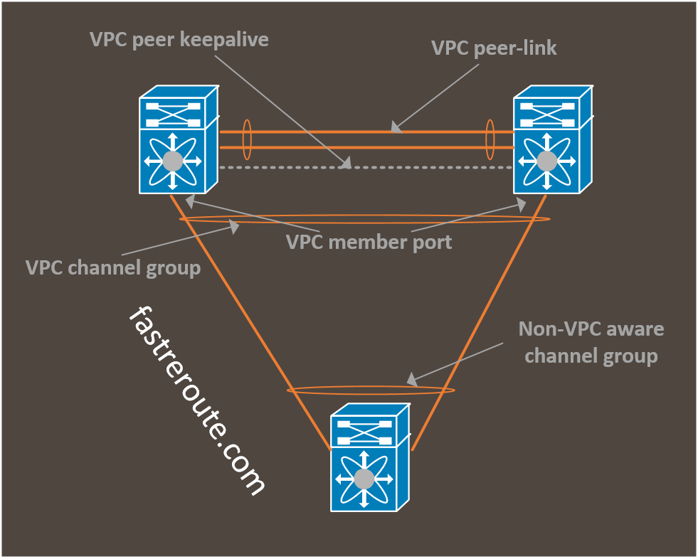
VPC channel group – is similar to traditional EtherChannel, however, has its member ports on different switches
VPC port or VPC member port – is a port that is part of VPC-based port-channel
Without VPC, parallel links are considered as a Layer 2 loop. Spanning-Tree Protocol (STP) would block one of these links. To enable simultaneous use of these parallel links, STP priority adjustments were required and load balancing was done on per-VLAN or per-MST instance basis. Such configuration adds complexity and doesn’t provide even traffic distribution.
VPC addresses these issues. With VPC, multiple uplinks from an access switch are treated as a single link. Layer-2 topology becomes loop-free and no port blocking by Spanning Tree Protocol is required.
Servers and hypervisors can also more optimally balance traffic without having to pin virtual machines to a specific uplink.
VPC Components
To enable VPC a high-bandwidth interface known as VPC peer-link is required. It is recommended to bundle at least two 10Gbps ports. Peer-link is used to perform state synchronization and some data traffic.
An additional interface is required for keepalive exchange. It provides physically diverse connectivity, so heartbeats are not lost when VPC peer-link goes down. This mechanism protects against split-brain scenarios during VPC peer link failure.
Switches can be directly connected using 1Gbps or higher bandwidth ports. Out-of-band management interfaces also can be used as a peer-keepalive link.
Peer keepalives are sent every second by default and must be explicitly bound to a specific IP address. As a result, heartbeats can be routed across the network.
Nexus switches have dedicated mgmt0 interfaces for out-of-band management. This interface belongs to management VRF and designed to be connected to a dedicated Out-Of-Band Management (OOBM) network. Standard practice is using this network for peer-keepalives. This saves a front data port.
One of VPC peers becomes primary and the other one is secondary. The configurable priority value controls preference of a switch’s role, however, it is runtime parameter and secondary switch can become operational primary. Primary peer exclusively runs some of control plane features, but most importantly during peer link failures it keeps its interfaces up, while secondary has to shutdown links participating in VPC downstream to prevent loops.
As both VPC peers have their own management plane and configured separately, the protocol must ensure that both switches are configured in a consistent manner. There are 2 types of configuration parameters – Type 1 and Type 2. If Type 2 parameters mismatch both switches continue to operate normally, however, some traffic will be forwarded not optimally. With Type 1 settings mismatch, the secondary switch stops forwarding traffic for VPC enabled VLANs.
VPC VLAN – is VLAN that is allowed on VPC peer link
Orphan port – Port that is connected to a single switch and not part of a VPC port channel. To be qualified as an orphan port, it has to be a member of a VPC VLAN or have it enabled if it is 802.1q trunk.
The Data plane operation of the VPC switch pair follows some rules to prevent loops. During normal operations, peer-link is not used for data-plane packets with the exceptions of traffic to and from orphan ports or during one of the VPC member ports failure. VPC switches prefer local VPC ports when selecting egress interface.
VPC Configuration
Configuration of VPC consists of several steps:
- Prepare L3 peer-keepalive connectivity, in the example below, out-of-band management interface was used
- Enable VPC and LACP features
- Enable and configure global VPC options under “vpc domain” sub-mode. The most important settings are peer-keepalive and role priority (to make one of the switches a primary).
- Configure VPC peer-link
The diagram below shows the lab diagram and example of basic VPC configuration.
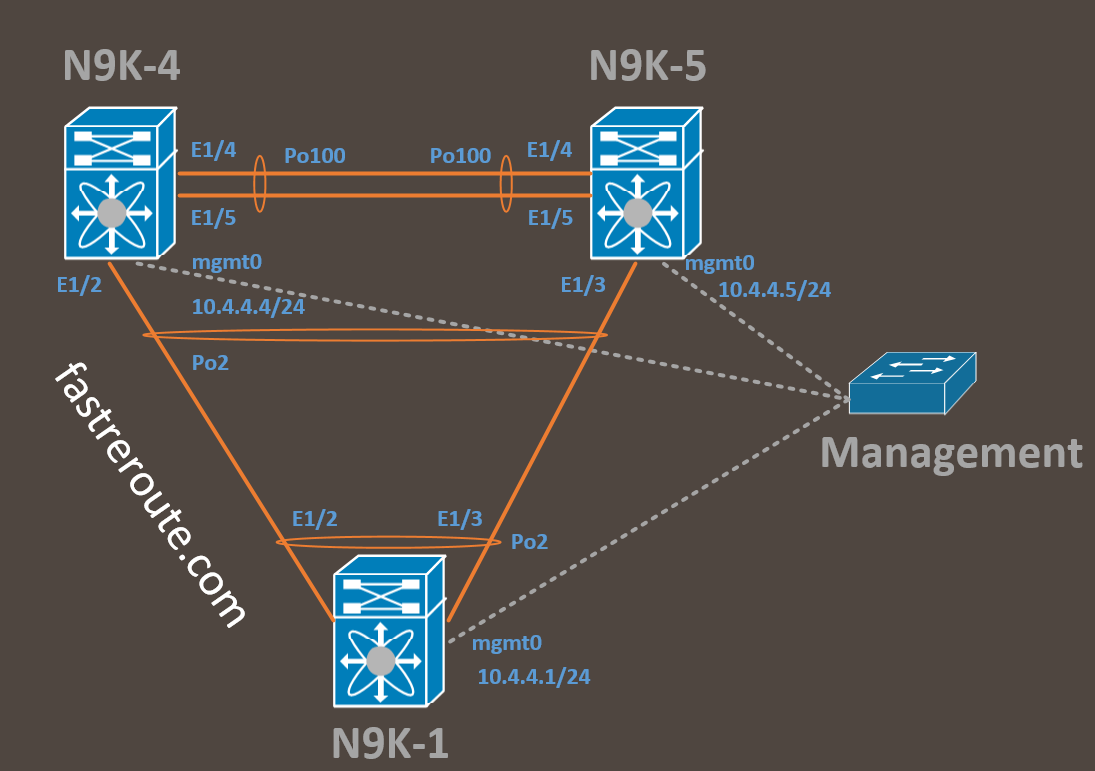
Sample configuration for VPC switches N9K-4 and N9K-5 is shown below.
| N9K-4 | N9K-5 |
|---|---|
| N9K-4(config)# interface mgmt0 N9K-4(config-if)# ip address 10.4.4.4/24 !Ensure that there is ip connectivity, see listing 1 |
N9K-5(config)# interface mgmt0 N9K-5(config-if)# ip address 10.4.4.5/24 |
| N9K-4(config)# feature vpc N9K-4(config)# feature lacp |
N9K-5(config)# feature vpc N9K-5(config)# feature lacp |
| N9K-4(config)# vpc domain 100 N9K-4(config-vpc-domain)# peer-keepalive destination 10.4.4.5 source 10.4.4.4 vrf management !To make this switch primary. Default is 32667 N9K-4(config-vpc-domain)# role priority 10 !See listing 2 for before and after verification |
N9K-5(config)# vpc domain 100 N9K-5(config-vpc-domain)# peer-keepalive destination 10.4.4.4 source 10.4.4.5 vrf management |
| N9K-4(config)# interface Po100 N9K-4(config-if)# switchport mode trunk N9K-4(config-if)# vpc peer-link N9K-4(config)# interface E1/4-5 N9K-4(config-if)# channel-group 100 mode active !See listing 3 for the verification successful VPC peering |
N9K-5(config)# interface Po100 N9K-5(config-if)# switchport mode trunk N9K-5(config-if)# vpc peer-link N9K-5(config)# interface E1/4-5 N9K-5(config-if)# channel-group 100 mode active |
| N9K-4(config-if)# int E1/2 N9K-4(config-if)# channel-group 2 mode active N9K-4(config-if)# int Po2 N9K-4(config-if)# vpc 2 !See listing 4 for the verification of connectivity to N9K-1 |
N9K-5(config-if)# int E1/3 N9K-5(config-if)# channel-group 2 mode active N9K-5(config-if)# int Po2 N9K-5(config-if)# vpc 2 |
N9K-4(config-if)# ping 10.4.4.5 vrf management
PING 10.4.4.5 (10.4.4.5): 56 data bytes
36 bytes from 10.4.4.4: Destination Host Unreachable
Request 0 timed out
64 bytes from 10.4.4.5: icmp_seq=1 ttl=254 time=14.936 ms
64 bytes from 10.4.4.5: icmp_seq=2 ttl=254 time=0.639 ms
64 bytes from 10.4.4.5: icmp_seq=3 ttl=254 time=0.497 ms
64 bytes from 10.4.4.5: icmp_seq=4 ttl=254 time=0.504 ms


--- 10.4.4.5 ping statistics ---
5 packets transmitted, 4 packets received, 20.00% packet loss
round-trip min/avg/max = 0.497/4.144/14.936 ms
N9K-4(config-vpc-domain)# show vpc
Legend:
                (*) - local vPC is down, forwarding via vPC peer-link


vPC domain id                     : 100
Peer status                       : peer link not configured
vPC keep-alive status             : Suspended (Destination IP not reachable)
Configuration consistency status  : failed
Per-vlan consistency status       : failed
Configuration inconsistency reason: vPC peer-link does not exist
Type-2 consistency status         : failed
Type-2 inconsistency reason       : vPC peer-link does not exist
vPC role                          : none established
Number of vPCs configured         : 0
Peer Gateway                      : Disabled
Dual-active excluded VLANs        : -
Graceful Consistency Check        : Disabled (due to peer configuration)
Auto-recovery status              : Disabled
Delay-restore status              : Timer is off.(timeout = 30s)
Delay-restore SVI status          : Timer is off.(timeout = 10s)
Operational Layer3 Peer-router    : Disabled


!After peer-keepalive configured on both switches


N9K-4(config-vpc-domain)# show vpc
Legend:
                (*) - local vPC is down, forwarding via vPC peer-link


vPC domain id                     : 100
Peer status                       : peer link not configured
vPC keep-alive status             : peer is alive
Configuration consistency status  : failed
Per-vlan consistency status       : failed
Configuration inconsistency reason: vPC peer-link does not exist
Type-2 consistency status         : failed
Type-2 inconsistency reason       : vPC peer-link does not exist
vPC role                          : none established
Number of vPCs configured         : 0
Peer Gateway                      : Disabled
Dual-active excluded VLANs        : -
Graceful Consistency Check        : Disabled (due to peer configuration)
Auto-recovery status              : Disabled
Delay-restore status              : Timer is off.(timeout = 30s)
Delay-restore SVI status          : Timer is off.(timeout = 10s)
Operational Layer3 Peer-router    : Disabled
N9K-4(config-vpc-domain)#
N9K-4(config-if)# show vpc
Legend:
                (*) - local vPC is down, forwarding via vPC peer-link


vPC domain id                     : 100
Peer status                       : peer adjacency formed ok
vPC keep-alive status             : peer is alive
Configuration consistency status  : success
Per-vlan consistency status       : success
Type-2 consistency status         : success
vPC role                          : primary
Number of vPCs configured         : 0
Peer Gateway                      : Disabled
Dual-active excluded VLANs        : -
Graceful Consistency Check        : Enabled
Auto-recovery status              : Disabled
Delay-restore status              : Timer is off.(timeout = 30s)
Delay-restore SVI status          : Timer is off.(timeout = 10s)
Operational Layer3 Peer-router    : Disabled


vPC Peer-link status
---------------------------------------------------------------------
id    Port   Status Active vlans
--    ----   ------ -------------------------------------------------
1     Po100  up     1
N9K-1(config)# feature lacp
N9K-1(config)# interface E1/2-3
N9K-1(config-if-range)# channel-group 2 mode active


N9K-1(config-if-range)# show port-channel summary
Flags:  D - Down        P - Up in port-channel (members)
        I - Individual  H - Hot-standby (LACP only)
        s - Suspended   r - Module-removed
        b - BFD Session Wait
        S - Switched    R - Routed
        U - Up (port-channel)
        p - Up in delay-lacp mode (member)
        M - Not in use. Min-links not met
--------------------------------------------------------------------------------
Group Port-       Type     Protocol  Member Ports
      Channel
--------------------------------------------------------------------------------
2     Po2(SU)     Eth      LACP      Eth1/2(P)    Eth1/3(P)
N9K-4(config-if)# show vpc
Legend:
                (*) - local vPC is down, forwarding via vPC peer-link


vPC domain id                     : 100
Peer status                       : peer adjacency formed ok
vPC keep-alive status             : peer is alive
Configuration consistency status  : success
Per-vlan consistency status       : success
Type-2 consistency status         : success
vPC role                          : primary
Number of vPCs configured         : 1
Peer Gateway                      : Disabled
Dual-active excluded VLANs        : -
Graceful Consistency Check        : Enabled
Auto-recovery status              : Disabled
Delay-restore status              : Timer is off.(timeout = 30s)
Delay-restore SVI status          : Timer is off.(timeout = 10s)
Operational Layer3 Peer-router    : Disabled


vPC Peer-link status
---------------------------------------------------------------------
id    Port   Status Active vlans
--    ----   ------ -------------------------------------------------
1     Po100  up     1


vPC status
----------------------------------------------------------------------------
Id    Port          Status Consistency Reason                Active vlans
--    ------------  ------ ----------- ------                ---------------
2     Po2           up     success     success               1