Cisco SD-Access Components
I’ve posted earlier overview articles about Cisco’s WAN and Data Center software-defined technologies – Cisco Viptela SD-WAN (link) and ACI (link). Now it’s time to explore the solution for LAN. Cisco SD-Access is the evolutionary step in how campus networks are built and operated. In this blog post, we will discover components of Cisco SD-Access, namely control and data plane elements.
What are the main SD-Access benefits?
The key advantage of a software-defined solution is management centralization. DNA Center with SD-Access application simplifies campus network operation by providing a single point of management for multiple devices. DNA Center not only automates devices configuration but also exposes APIs, so it can be accessed programmatically.
With Cisco SD-Access administrators can create and apply common policies across the entire campus network. Operational expense savings is one of the main selling points of the Cisco SD-Access.
Network flow telemetry gives operators better visibility into what is happening in the network. Cisco ISE and TrustSec provide user and device identification and segmentation within the same virtual network boundary. SD-Access can also support fully isolated virtual networks, for example, between multiple tenants. As a result better security is achieved with less effort.
Components of Cisco SD-Access
SD-Access consists of 3 categories of components:
- Network fabric – Switches, routers, wireless LAN controllers and access points. Routed access with VXLAN data plane and LISP control plane
- Cisco DNA Center with SD-Access – one or multiple appliances
- Cisco ISE – one or multiple appliances
Check this document for detailed information on supported component combinations and licensing requirements (external link).
This link is an official matrix listing compatibility between versions of different components.
SD-Access Fabric
Switches and Routers
Different roles that switches can perform will be covered in later sections of this article. However, for the purpose of right platform selection 2 main switch roles should be considered – Edge and Border/Control plane nodes.
Edge switches are similar to access switches, as they have end-user devices connected to them and platforms that currently recommended (Catalyst 9000) and supported (other platforms; check the release notes and licensing documentation for feature support) are listed below:
- Catalyst 9000-series: 9200, 9300, 9400, 9500
- Catalyst 3850 and 3650
- Catalyst 4500E: Sup 8-E, 9-E
Border/Control plane switches perform Endpoint ID tracking and are responsible for running Layer 3 routing with networks outside of the fabric. Therefore, these switches have higher memory requirements. If only control plane operation to be implemented with no traffic transit routing virtual CSR 1000v can be used. And when border node functions without control plane operations are required Nexus 7700 is a supported option.
Border/Control plane switches and routers to choose from are:
- Catalyst 9000-series: 9300, 9400, 9500, 9600
- Catalyst 3850
- Catalyst 6500/6807-XL: Sup 2T, 6T
- Catalyst 6840-X, 6880-X
- Nexus 7700: Sup 2-E, 3-E, M3 line cards only – border functionality only
- ISR 4300, 4400
- ASR 1000-X, 1000-HX
- CSR 1000v
Fabric Wireless Controllers and Access Points
SD-Access supports traditional WLCs and APs without integration with fabric and they communicate between each other in overlay over-the-top as any other data traffic. Fabric-integrated Wireless Controllers and Access Points participate in the control plane and data flow is changed in comparison with traditional WLCs and APs.
This integration provides additional benefits and better efficiency. For example, user traffic from a fabric access point is de-capsulated on the edge switch without tunneling it up to its WLC. This section lists supported fabric-integrated wireless components.
Supported WLCs are:
- Catalyst 9800 Wireless Controller: 9800-40, 9800-80, 9800-CL and Embedded on C9300, C9400 and C9500
- Cisco 3504, 5520 and 8540 WLC
Fabric mode APs must be directly connected to a fabric edge node. Supported models are:
- WiFi 6 APs: Catalyst 9115AX, 9117AX and 9120AX
- Wave 2 APs: Aironet 1800, 2800 and 3800
- Wave 2 APs, outdoor models: Aironet 1540, 1560
- Wave 1 APs: Aironet 1700, 2700 and 3700
- Aironet 4800 APs
DNA Center
DNA Center is responsible for fabric management. The software must be installed on a physical DNA Center Appliance which is based on the Cisco UCS C-series Server. SD-Access is one of the applications of DNA Center.
Check this article dedicated to DNA Center role and functions.
If DNA Center appliance becomes unavailable fabric would continue to function, however, automatic provisioning will be impacted. For redundancy, a highly available cluster of 3 nodes of the same model is recommended.
DNA Center Appliances have 3 options to choose from:
- Entry-level of up to 1,000 devices: DN2-HW-APL (C220 M5, 44 cores)
- Mid-size of up to 2,000 devices: DN2-HW-APL-L (C220 M5, 56 cores)
- Large of up to 5,000 devices: DN2-HW-APL-XL (C480 M5, 112 cores)
Identity Services Engine (ISE)
Cisco Identity Services Engine (ISE) provides identity services for the solution. Access control policies which are based on user and device identity are also ISE’s responsibility. With Cisco TrustSec edge device applies Security Group Tags (SGTs) on the traffic based on the identity. Then these tags can be used to perform filtering using SGT-based access-lists.
ISE is available as a virtual or a physical appliance. The following models of ISE appliances are available:
- Small physical: SNS-3515
- Large physical: SNS-3595
- Small virtual: R-ISE-VMS
- Medium virtual: R-ISE-VMM
- Large virtual: R-ISE-VML
ISE appliances can also be implemented in a high-availability setup with load balancing achieved by splitting functions between nodes.
Cisco ISE integrates with DNA Center using REST API and PXGrid. DNA uses REST API to automate policy configuration on ISE and PXGrid is used for endpoint information exchange.
Data Plane
Figure 1 shows a sample network. Fabric is shown in a blue rectangle. Fabric switches in SD-Access are connected to each other using Layer 3 links. These links establish underlay or transport networks.
Switch fabric physical topology can follow traditional access-distribution-core patterns. There is no requirement to connect switches in leaf-and-spine topology as in data center underlay. Campus networks usually don’t need to accommodate intensive east-west communication as data centers do.
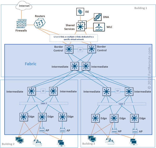
On top of the underlay, virtual networks are created with the use of VXLAN encapsulation. This is similar to the way how modern data center switch fabrics are built, such as Cisco ACI or native Cisco NX-OS VXLAN fabrics.
Packets on inter-switch links will be encapsulated in UDP on the transport layer and have source and destination IP addresses of Edge device loopbacks called routing locators or RLOCs. Edge nodes are responsible for VXLAN encapsulation/decapsulation when sending and receiving traffic towards fabric.
For broadcast/unknown unicast/multicast or BUM traffic, underlay can either use headend replication or in newer versions of SD-Access multicast in underlay can be utilized.
End-user devices connected to downstream ports of edge switches don’t see any difference from traditional Ethernet networking. The only exception is fabric access points. They must be attached to fabric edge nodes and VXLAN encapsulation is extended down to access points.
To deliver a packet, edge nodes sends a query to the control node to determine the target edge’s node IP address (RLOC) using LISP. If a reply is received, the edge node encapsulates traffic into VXLAN datagram and sends it directly to the destination node. If the query cannot be resolved, for example, in the case when the destination is not fabric-attached then traffic is sent to the default border node which in turn performs normal route lookup.
Control Plane
Fabric runs multiple control-plane protocols which can be divided into several categories:
- Underlay network protocols
- Endpoint ID tracking protocol
- External to fabric routing protocols
- WLC-related protocols
Underlay Protocols
The main task of the underlay is to ensure that edge devices can reach each other via their RLOCs or IP addresses that are used in the VXLAN IP header. SD-Access supports automated provisioning with IS-IS and it is recommended for greenfield deployment. It can, however, be replaced with OSPF or EIGRP with manual configuration.
The other protocol that can be used in underlay is a multicast routing protocol to replace resource and bandwidth-intensive headend replication. PIM-SM is the supported protocol.
All switches in the fabric run underlay protocols. Intermediate routers are similar to P routers in MPLS in the way that they work only with outer IP packet headers. Therefore, they don’t need to run or understand any other protocols described in the next sections.
Endpoint ID tracking
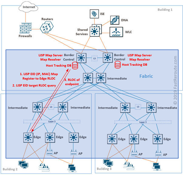
Endpoint IDs are IP and MAC addresses of devices connected to edge nodes. The SD-Access control plane is based on the Locator ID Separation Protocol (LISP).
Each designated control plane node performs LISP Map-Server (MS) and Map-Resolver (MR) roles.
Edge nodes register endpoints by sending Map-Register message to a control plane node. Map-Server stores endpoint ID to edge device information in Host Tracking Database (HTDB).
When the edge node needs to find the address of the edge device behind which specific endpoint is located, it sends a query to Map-Resolver. After checking HTDB, MR sends back RLOC for the requested endpoint.
Control plane and border node functionality can coexist on the same device and each should be deployed on at least two devices for redundancy.
External to fabric routing protocols
Control nodes know all endpoints connected to a fabric using the process described above. If an endpoint is not in HTDB and cannot be resolved, the edge node will assume that it is outside of the fabric and forward such traffic to the default fabric border node.
Border nodes connect the fabric to external networks and BGP is the recommended protocol to run on the boundary. Border nodes are also responsible for SGT propagation outside of the fabric.
There are 3 types of border nodes in SD-Access:
- External. Default exit from fabric with no specific routes injection
- Internal. Gateway only for a set of networks, such as shared services prefixes
- Anywhere. Combination of external and internal functionality
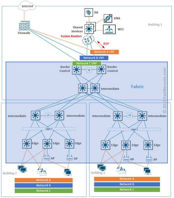
With multiple virtual networks overlaid on top of the SD-Access fabric, isolation on the fabric border is achieved with the use of VRFs.
Access to shared services, such as Cisco DNA Center, WLC controllers, DNS and DHCP servers are required from both underlay and overlay. Such access can be provided by connecting fusion routers to border nodes with VRF-lite. Fusion routers perform route leaking between VRFs to provide reachability information to the shared services from the fabric.
WLC-related protocols
Fabric-integrated WLCs run traditional control plane protocols, such as CAPWAP tunneling from APs to the WLC. However, CAPWAP tunnels are not used for data traffic and WLC doesn’t participate in user traffic forwarding.
When a client connects to a fabric enabled access point, the LISP registration process is different from described above for wired clients. With fabric APs, registration is not performed by the access point or the edge switch. Instead, WLC performs proxy registration with the LISP Map-Server in HTDB. If a wireless client roams, WLC ensures that the LISP mapping is updated.