Cisco SD-WAN Direct Internet Access (DIA) Step by Step
SD-WAN deployments use the Internet as the transport to replace WAN networks traditionally designed to leverage centralized Internet access via the data center. Direct Internet Access (DIA) refers to the configuration when Internet-facing traffic breaks out directly from the branch router.
Is Network Address Translation (NAT) required for DIA to operate? Yes, NAT maintains a translation table, that tracks outbound sessions from the service side VPNs (LAN), so the return traffic can be sent back without having to leak service VPN routes into VPN 0.
In the Cisco SD-WAN solution, transport-facing and user-facing interfaces belong to different VPNs or VRFs. VPN 0 contains transport (or underlay) network-facing interfaces, such as Internet and MPLS. Service-side VPNs contain user-facing interfaces.
The figure below shows logical VPN isolation within a router. In the routing table of VPN 0, there will be no entries for subnets where Host A and Host B are located. These subnets can even have the same IP addresses.
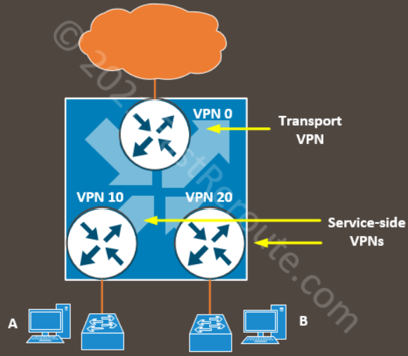
For DIA to work we need to allow traffic to flow between these virtual routers (or VPNs). To direct traffic from service-side VPNs we can use either static routes or a centralized data policy. NAT in transport VPN allows return traffic to be sent back.
Direct Internet Access on Cisco SD-WAN platforms is enabled in 2 steps. The first one is the NAT configuration on the transport interface. The second step directs traffic from service-side VPN using either a static route or centralized data policy.
Step 1: Enable NAT on the transport interface
Let’s start with a very basic topology, shown in Figure 2.
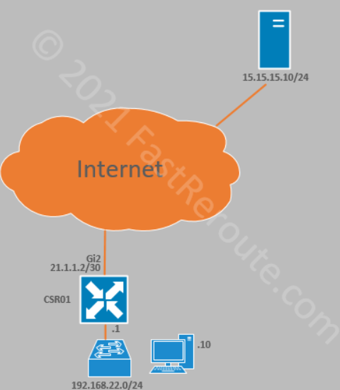
Edge router has a device template assigned, which references a basic set of feature templates required to provide connectivity.
The first step of both static route and policy-based configuration is to enable NAT on an interface in the transport VPN – GigabitEthernet2. This is done by adjusting the interface template.
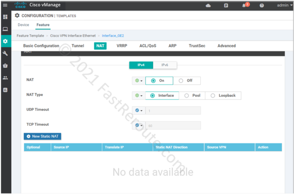
The following commands are pushed to the device.
ip nat inside source list nat-dia-vpn-hop-access-list interface GigabitEthernet2 overload
ip nat translation tcp-timeout 3600
ip nat translation udp-timeout 60
interface GigabitEthernet2
  ip nat outside
We couldn’t find a way to modify the nat-dia-vpn-hop-access-list used in ip nat inside command. This ACL is not visible in the running configuration or in the output of show ip access-lists. In IOS-XE this access list identifies traffic to be translated. In SD-WAN, however, to achieve this data policy needs to be configured.
Step 2: Direct traffic from service-side VPN
There are 2 ways to achieve this:
- Static route in service VPN template
- Centralized data policy
Step 2 (option 1): Static Route Configuration
Let’s configure a static default route under VPN 1 (Service VPN). Note that VPN is selected as a gateway option.
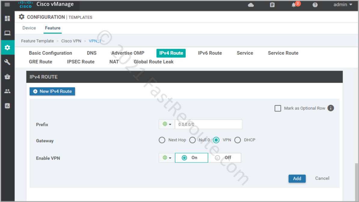
The static route command that is pushed to the device looks like this:
ip nat route vrf 1 0.0.0.0 0.0.0.0 global
Note that the static route command has nat keyword. If we turn off NAT enabled in the previous step, the route will disappear. This essentially means that you have to do address translation for the configuration to work.
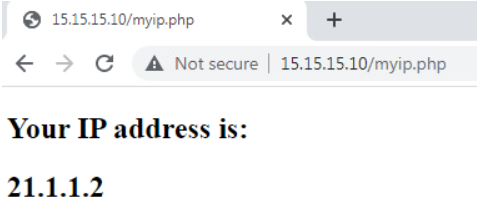
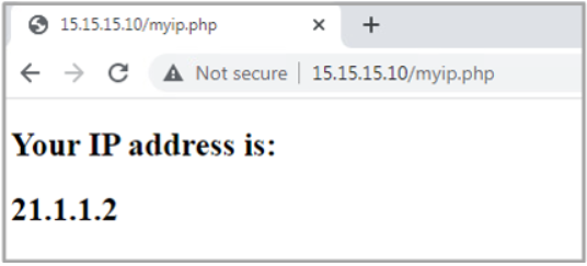
Let’s do the test from our test PC, confirming that the remote server sees the request as it’s coming from the router’s external IP address.
To check the list of translations, we can run the following command on the router:
CSR01#show ip nat translations verbose
Pro  Inside global         Inside local          Outside local         Outside global
tcp  21.1.1.2:5062         192.168.11.10:49158   15.15.15.10:80        15.15.15.10:80
  create: 11/14/21 23:16:21, use: 11/14/21 23:16:27, timeout: 00:00:56
  RuleID : 1
  Flags: timing-out
  ALG Application Type: NA
  WLAN-Flags: unknown
  Mac-Address: 0000.0000.0000    Input-IDB:
  VRF: 1,  entry-id: 0xe9f7f840, use_count:1
  In_pkts: 7 In_bytes: 978, Out_pkts: 7 Out_bytes: 982
  Output-IDB: GigabitEthernet2
CSR01#show ip nat translation
Pro  Inside global         Inside local          Outside local         Outside global
tcp  21.1.1.2:5062         192.168.11.10:49158   15.15.15.10:80        15.15.15.10:80
Step 2 (option 2): Centralized policy
We have removed the static route created in Step 2 (option 1), as the traffic will be directed by the centralized policy.
To implement DIA we will configure the traffic data section of the centralized policy that will match traffic coming from 192.168.11.0/24 (LAN segment) to 15.15.15.10/32 (the webserver).
Only one centralized policy can be activated globally at a time. The centralized policy contains multiple component policies. In this example, we will define a data policy, which then can be applied to a site list. In the following steps, we will create a new policy.
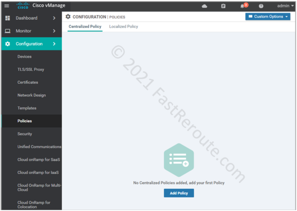
Create a centralized policy
Navigate to Configuration > Policies and click on Add Policy button.
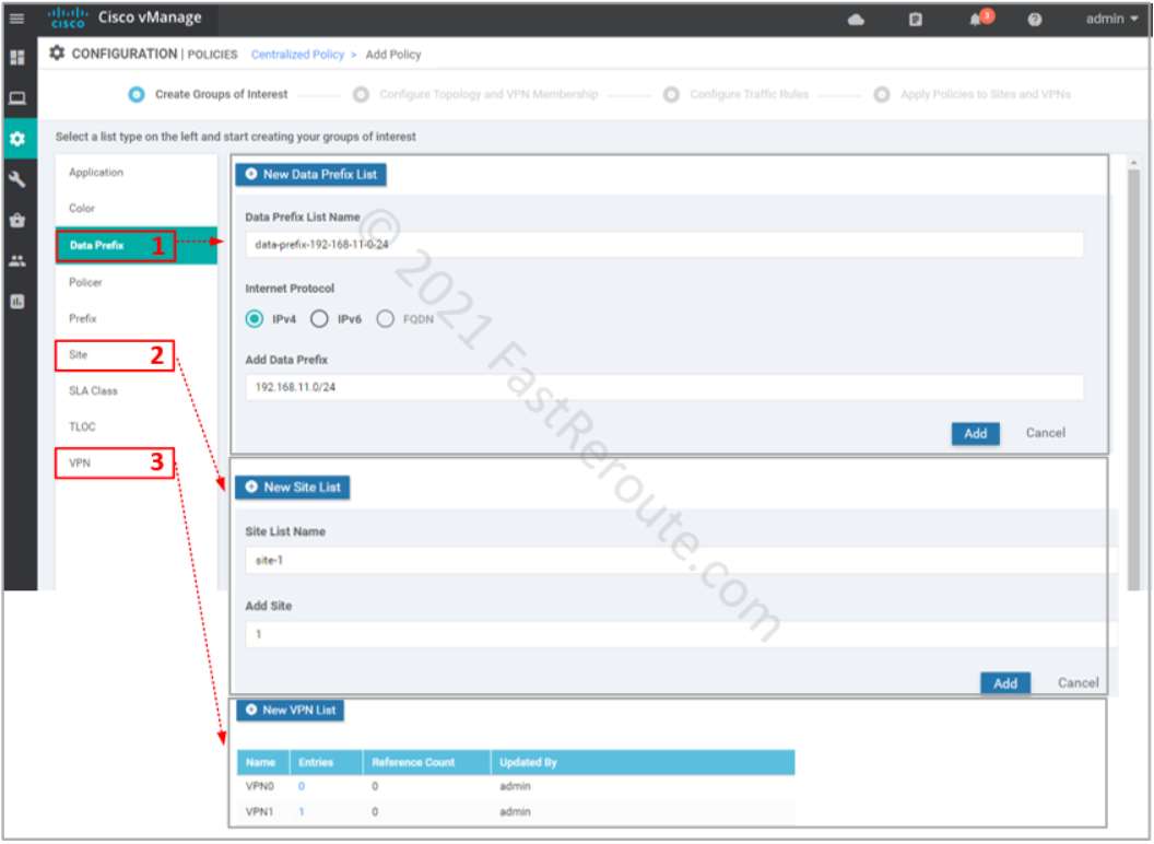
The first step of creating a policy is called “Create Groups of Interest”. These are variables that we can later use in the policy. For our example, we will define:
- Data Prefix – for source prefix 192.168.11.0/24, and we will use 15.15.15.10/32 directly in our traffic matching configuration without variable definition
- Site List – we want apply only to a single site with Site ID of 1; it is recommended not to have the same site in multiple site lists to ensure that only 1 policy of each type is applied to that site
- VPN List – service VPN 1
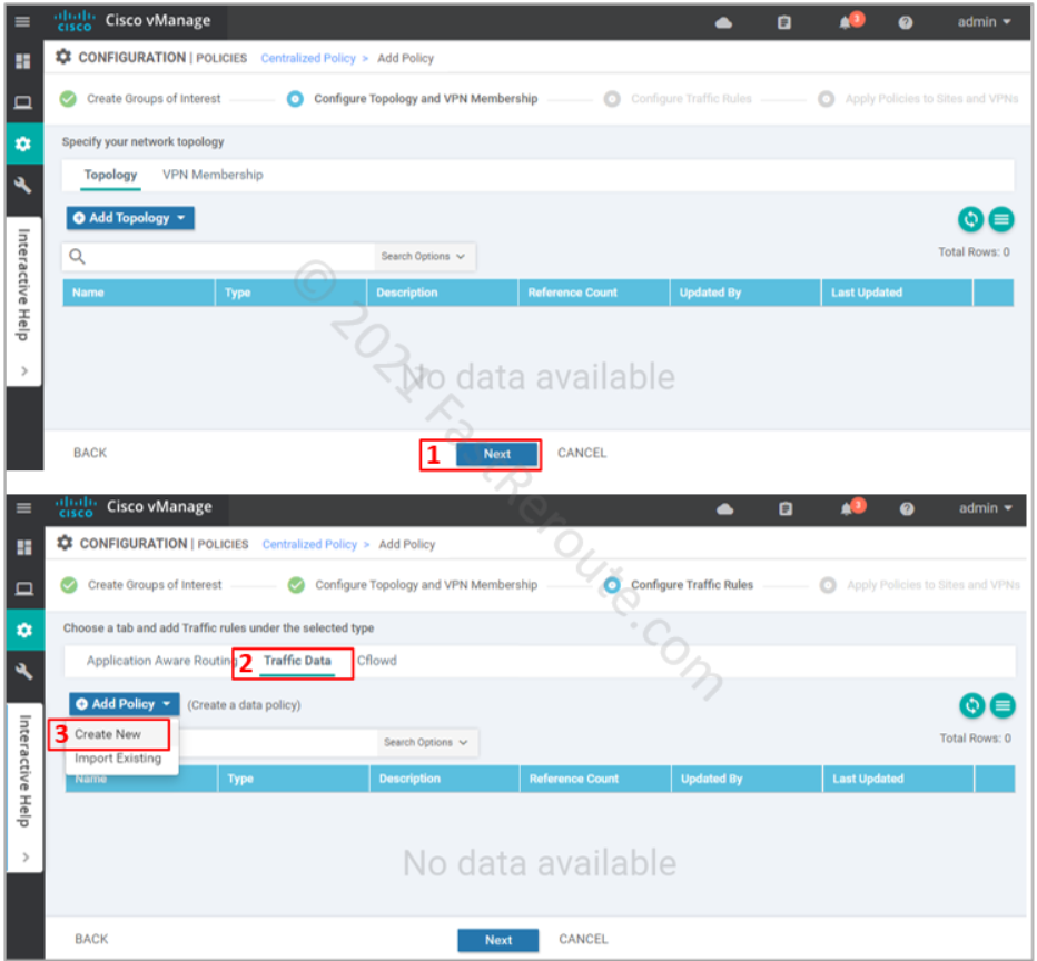
After defining all required variables and pressing the Next button, we are moved to the Topology and VPN Membership section of the wizard (see the top part of the screenshot below). We don’t need to configure anything for our data policy, so we just press Next.
On the Configure Traffic Rules step of the wizard click on the “Traffic Data” section of the policy, click on Add Policy > Create New (refer to the bottom part of the next screenshot).
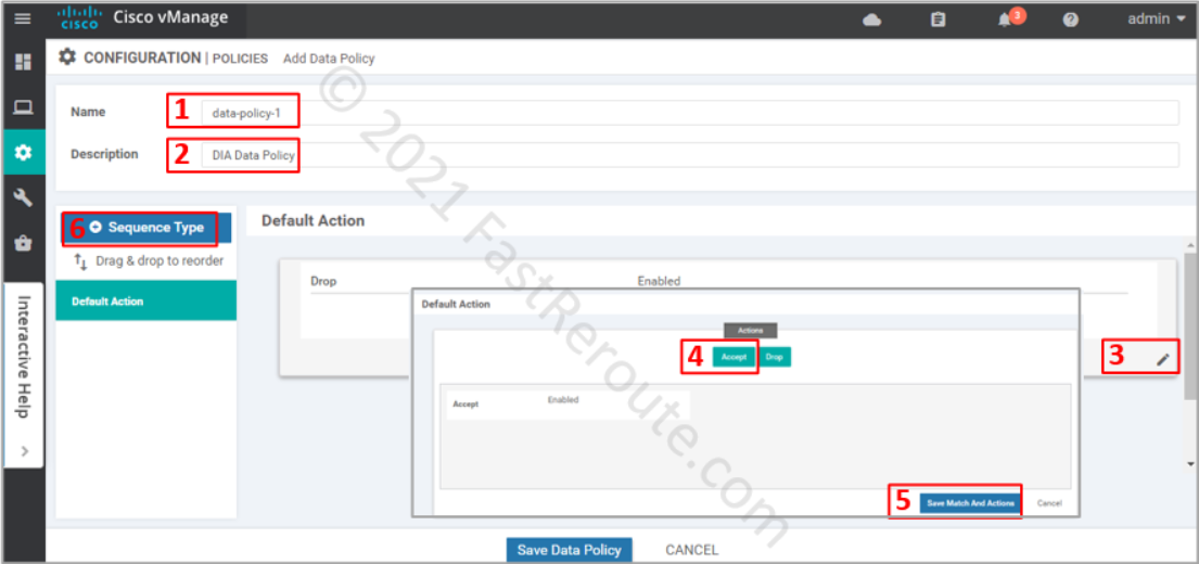
In a new data policy window enter the name and description of the policy. Adjust the default action to Accept to ensure that the packets that don’t match our criteria for DIA will not be dropped. Finally, press + button to add a rule that will be matching DIA traffic and apply NAT to it.
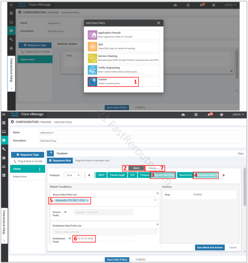
In the pop-up window select Custom policy. The other options are just a subset of the match and set conditions tailored for different scenarios, custom lists all of them.
Custom rule is added on top of the default action. If there are several rules, you can re-arrange them on the left panel. Ensure that the Match section is selected, add Source and Destination data prefixes to set the conditions for the rule.
Select the data prefix that we set up earlier in groups of interest as the source. Type-in destination as the actual address without the use of the variable. Both options lead to the same result, however, the use of variables allows you to use descriptive naming of the object plus adjusting the values outside of the policy configuration. Click on the Actions button.
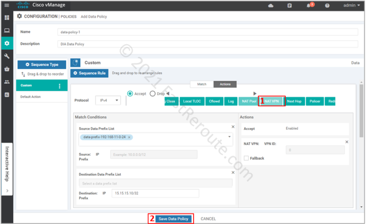
Select NAT VPN action, as shown in the following screenshot. The fallback option is useful when you want this traffic to follow the routing table when NAT cannot be used, for example, when the interface is down. Press the “Save data policy” button.
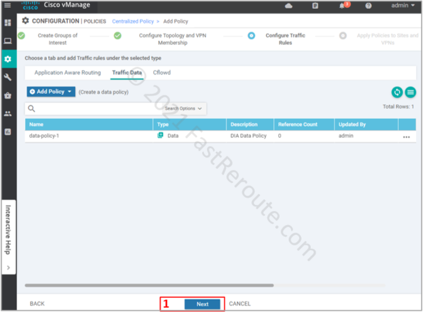
The next screenshot list the data policy that we built in the previous step. Notice that the reference count is 0, as we haven’t yet applied it yet. Press Next.
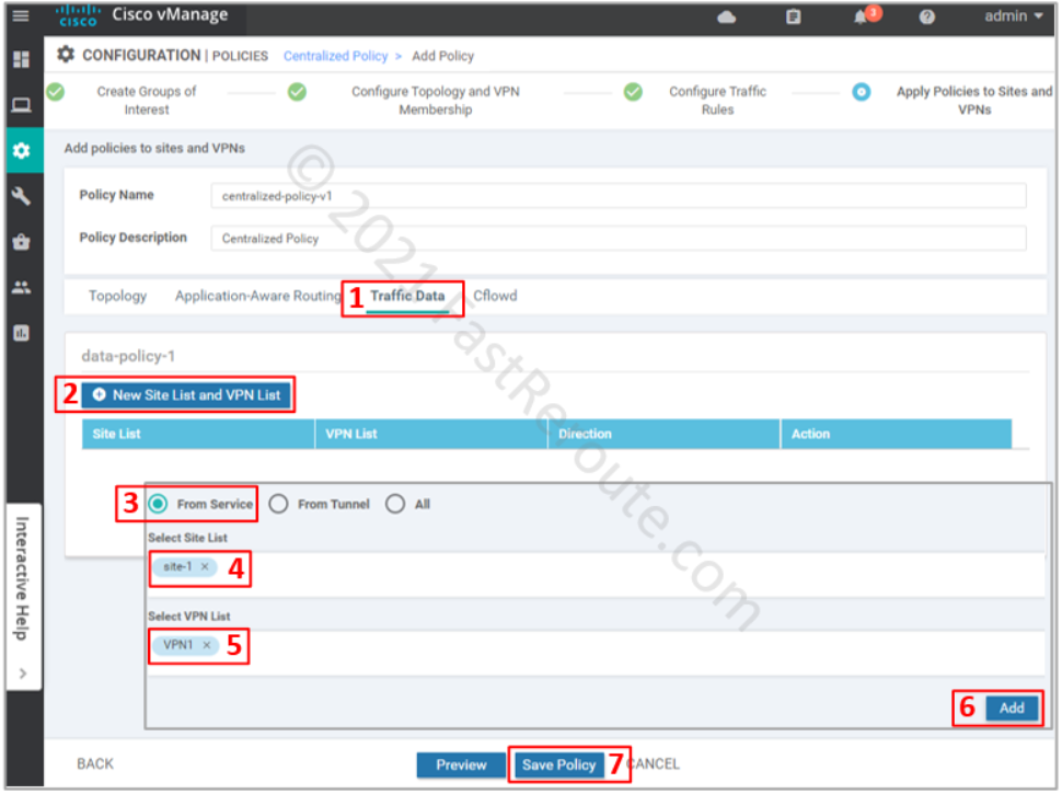
The final step is to apply the policy. Click on the Traffic Data section, and then under data-policy-1 press “New Site List and VPN List”. In the pop-up window select “From Service” direction, site-1 as the site list, and VPN1 as the VPN list. Press the Save Policy button.
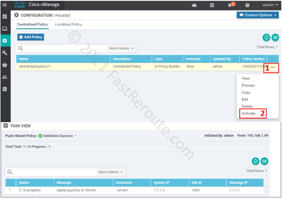
The final step is to activate the policy.
At this stage vManage will push the policy to vSmart as part of its running-config:
vsmart# show running-config
<output omitted>
policy
 data-policy _VPN1_data-policy-1
  vpn-list VPN1
   sequence 1
    match
     source-data-prefix-list data-prefix-192-168-11-0-24
     destination-ip          15.15.15.10/32
    !
    action accept
     nat use-vpn 0
    !
   !
   default-action accept
  !
 !
 lists
  vpn-list VPN1
   vpn 1
  !
  data-prefix-list data-prefix-192-168-11-0-24
   ip-prefix 192.168.11.0/24
  !
  site-list site-1
   site-id 1
  !
 !
!
apply-policy
 site-list site-1
  data-policy _VPN1_data-policy-1 from-service
 !
vSmart will use OMP to distribute the policy to edge routers. In contrast to vSmart, edge routers will not display the policy in the running configuration. Use show sdwan policy from-vsmart command instead.
CSR01#show sdwan policy from-vsmart
from-vsmart data-policy _VPN1_data-policy-1
 direction from-service
 vpn-list VPN1
  sequence 1
   match
    source-data-prefix-list data-prefix-192-168-11-0-24
    destination-ip          15.15.15.10/32
   action accept
    nat use-vpn 0
    no nat fallback
  default-action accept
from-vsmart lists vpn-list VPN1
 vpn 1
from-vsmart lists data-prefix-list data-prefix-192-168-11-0-24
 ip-prefix 192.168.11.0/24
Let’s check from the client machine that NAT works: