Compare and Contrast Collapsed Core and Three-Tier Architectures
Update: check our new article for new CCNA exam blueprint.
The next topic from the CCNA routing and switching blueprint that I thought would be interesting to go through is LAN-design related:
1.5 Compare and contrast collapsed core and three-tier architectures
While there might be more modern approaches for LAN or Campus designs, for the purpose of this specific exam objective let’s start with three-tier architecture. The 3 tiers are – Access, Distribution, and Core. Tiers are logical, so it doesn’t have to be a dedicated device on each one of them.
Access layer exists in every design because it’s where end devices, such as computers and phones are connected. QoS classification and marking, 802.1X authentication is performed on access tier switches, as these services should be applied as close to the source as possible. Access switches usually have high copper port density and Power Over Ethernet functionality for the phones and access points.
What are the current LAN access platforms? Catalyst 2960-X/XR (can be stackable), Catalyst 3650 (can be stackable), and Catalyst 3850 (stackable), Catalyst 9300 (stackable), and Catalyst 9400 (modular).
If the network only has a requirement of 20 ports, are dedicated distribution and core tier devices required? Probably not. What if there 200 end-user devices? It may or may not be required – depends on several factors. If all 200 devices are on the same floor and copper-based cabling can reach each device from a single communications room, then 5 x 48 port stackable switches might be sufficient and no dedicated distribution layer device is required.
The distribution tier performs aggregation of links from access switches and can be thought of as the hub with access switches being spokes. Distribution switches are responsible for providing L3 routing for access tier and access-lists application.
It is a better design approach than, for example, flat networks with switches connected in a daisy-chained fashion. The benefits of such star-like topology are a predictable number of hops and consistent performance with known oversubscription ratio.
Links between access and distribution switches can be either Layer 2 or Layer 3. L2 is a more traditional way, as originally access tier platforms didn’t have routing capabilities. Having switched links gives network administrators the ability to extend VLANs across multiple access layer switches.
The purpose of the core is to route traffic between distribution switches as efficiently as possible, so usually, there is no additional processing done in the core. The core layer switch’s responsibility is to connected multiple pairs of distribution switches in different buildings together across the campus. Uplinks from the distribution to the core and within the core are Layer 3 based.
If there is a single building, or all-access switches can be connected to the same pair of distribution switches, then the core device is not required. The other scenario where there are multiple buildings, but if all distribution switches can be connected to each other, then L3 links between these switches represent the core. Such architecture is called a collapsed core.
Current switch platforms at the distribution and core layers are: Catalyst 3850 (stackable), Catalyst 4500-X, Catalyst 6500 (modular), Catalyst 6800 (modular), Catalyst 9400 (modular), Catalyst 9500 (modular).
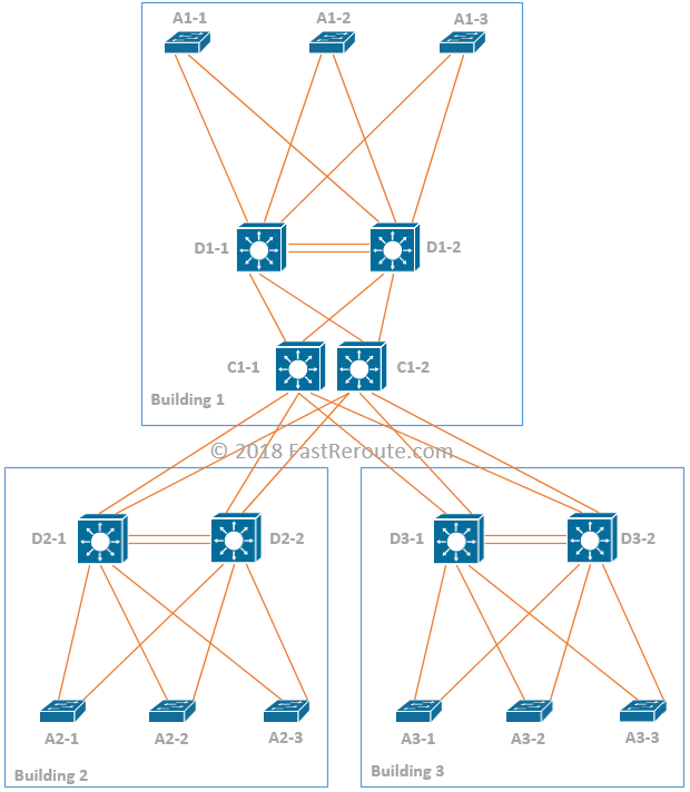
Let’s do a case study design. Figure 1 shows the example topology of campus with 3 buildings. Building 1 is the main building hosting the enterprise on-premises data center. Devices are named as TB-N, where T is the tier of the device, B is the building number, and N is a number of the device within each of the buildings. Each building has 2 distribution and 3 access switches.
To demonstrate different design decisions, each building will have different topology internally. Building 1, has a set of VLANs (100 and 200) that are spanned across all switches. Access to distribution links in this scenario must be Layer 2 based, as cross-switch VLAN extension is required. There might be other options if L2 overlaying is used, but we only considering classical Ethernet in this example.
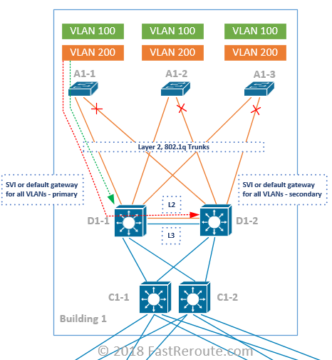
First hop routing will be performed on the distribution switches. As there are 2 of them, the first-hop redundancy protocol is required. Let’s assume that HSRP is in use.
The next question is if the inter-distribution switch link should be Layer 2 or Layer 3? To find the answer, let’s consider when this link will be used. There will be some control plane traffic within each VLAN between distribution switches, for example, HSRP packets for keepalive.
Data plane traffic for a single VLAN will converge on a single distribution switch based on STP priority, let’s say D1-1. In this case, A1-1 users in VLAN 200 can reach A1-2 and A1-3’s VLAN 200 via single-hop through D1-1. For traffic leaving the VLAN, it will need to reach the primary HSRP gateway.
The green path in the diagram describes the optimal traffic flow for inter-VLAN traffic. To achieve this primary HSRP gateway must be STP root for a specific VLAN. The red path in the diagram shows ineffective data flow that can result when the STP root is not active HSRP forwarder.
So there shouldn’t be any data traffic flowing via inter-distribution link during normal conditions. What happens if the link between A1-3 and D1-1 fails? Then we either have to use the L2 link between D1-1 and D1-2 or some of the access layer switches must be used for transit. So the answer to the question is D1-1 and D1-2 will have Layer 2 link enabled and it should have more bandwidth than links to the switches downstream.
Let’s now consider Building 2. Each of the access switches has its own VLANs configured. Topology is similar to Building 1’s, however, now we can filter out VLANs on links between access and distribution, as Layer 2 is not spanning across switches. This simplifies Layer 2 topology, as the only point where Layer 2 loop can be introduced is D2-1 to D2-2, if we decide to enable this as Layer 2 link.
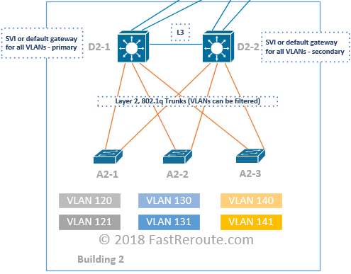
The link between distribution switches will not carry data traffic anymore even if one of the links fails. In fact, we want HSRP to move to the standby switch when a failure occurs, as there is only 1 switch downstream for each data VLAN. There will be some minimal amount of control plane traffic between D2-1 and D2-2 for HSRP that will utilize access switch as transit. So in this topology, we don’t need Layer 2 extension between distribution switches, so there is no STP blocking. As all the traffic traversing access to distribution switch links will be to and from the default gateway, the link to the standby HSRP gateway will be underutilized.
There is another common option with Layer 2 between Access and Distribution, which we will not cover as a separate example due to its simplicity. Let’s say you have D2-1 and D2-2 in either VSS setup or stacked together. Then each switch can aggregate its uplinks into a single port channel. In this case, from STP perspective topology is loop-free. The inter-distribution switch link will be running a proprietary protocol that will ensure that data plane forwarding is loop-free. Check my previous post for an overview of similar technology on Nexus Switches called VPC.
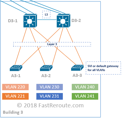
Building 3 has a topology where each VLAN is localized to a single switch similar to Building 2. However, in this scenario default gateways or SVIs for each VLAN are moved to corresponding access layer switch. There is no Layer 2 required between access and distribution and in most cases, it’s possible to evenly load balance traffic across both links.
Now we have a design for every building and it’s time to discuss core infrastructure. Core links are all L3 and are colored in blue. There are two core switches C1-1 and C1-2 and provide connectivity for all buildings, so there is no full mesh inter-building cabling is required.
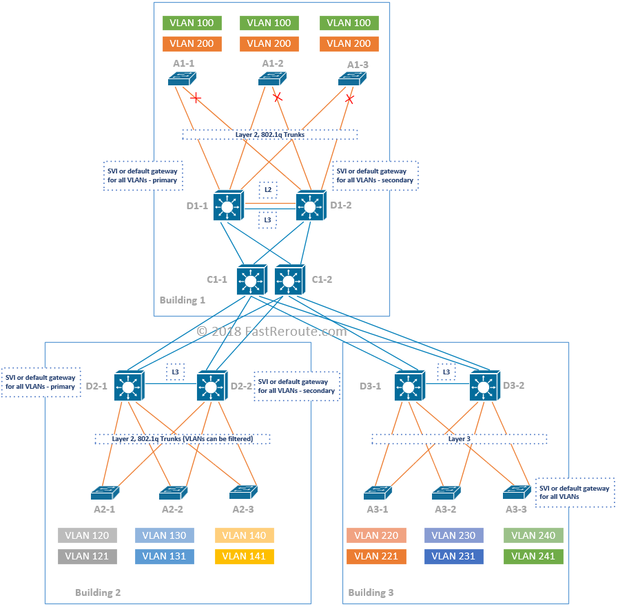
Notice that there are dedicated L3 links between each of the distribution switches in a pair. This link is required if one of the distribution switches loses its uplinks. For a single building setup, this link represents core tier functionality and the design is called collapsed core.
As it is Layer 3, all links can be utilized using equal-cost multi-pathing of the routing protocol (ECMP).