vSphere ESXi Networking Guide – Part 2: Standard Switches Configuration ESXi 6.7
This is the second part of the vSphere ESXi Networking Guide. In the previous post, we’ve discovered basic concepts and components of vSphere ESXi Standard Switches. This article shows how to create vSwitches step-by-step. The examples provided in the following sections are based on ESXi version 6.7.
There are several ways to configure a standard switch:
- With Direct Console User Interface (DCUI)
- Using Web-based vSphere Client of ESXi host or vCenter
- With PowerCLI
Refer to the diagram in Figure 1 for the sample topology that we will be building in this and the next articles. The environment consists of a single ESXi host running multiple VMs, which are grouped by their function as infrastructure, corporate and lab servers. The default port group called Management Network has a management port attached to it. To provide vMotion and iSCSI capability 2 extra ports and 2 port groups are configured.
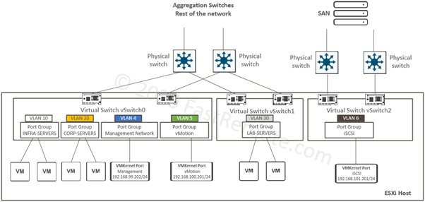
VLAN allocation for each port group is documented in the list below:
- Management – VLAN 4
- vMotion – VLAN 5
- iSCSI – VLAN 6
- INFRA-SERVERS – VLAN 10
- CORP-SERVERS – VLAN 20
- LAB-SERVERS – VLAN 30
The starting topology is a newly installed ESXi host with 6 physical adapters. Let’s assume that we’ve connected physical cables and enabled only a single port on the upstream switch. Figure 2 shows the switch port configuration. It is set up as an access port in VLAN 4, meaning that there will be no 802.1q tagged frames crossing this interface. We will change this port to tag traffic in the next section.
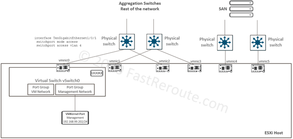
At this stage, the ESXi host has a single virtual switch, a single VM port group for virtual machines and a single VMKernel port for management.
The end state that we will achieve as the result of configuration steps in this article is shown in Figure 3.
Console Configuration (DCUI)
There is a limited number of things you can do with the network configuration via DCUI. The console is accessed by connecting a monitor and keyboard to ESXi host or by using out-of-band vendor-specific management options provided by the server, such as HP ILO or DELL DRAC. The main use case for this method of access is the initial setup or management access troubleshooting.
Press F2 on the initial screen and type in the username and password. Figure 4 shows available options available after the login.
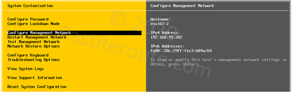
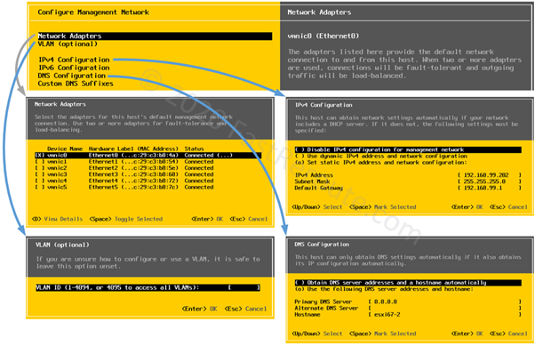
The next screenshot displays the Configure Management Network menu’s options and dialog windows. Network Adapters menu allows you to select physical NICs that will be used as uplinks for the default standard switch containing management port. VLAN and IPv4 Configuration settings are applied to the VMKernel ports and their group. As we don’t tag frames from the switch side, VLAN is left as unspecified.
DNS Configuration includes DNS server IPs, as well as ESXi host’s name.
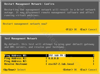
After changing any of the settings above, restart the management network to activate the changes using the menu shown in Figure 6, and perform optional testing.
The last network-related menu is Network Restore Options. As shown in the screenshot below, there are 3 available options:
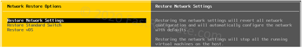
Restore Network Settings resets all network settings to their defaults. It removes vSwitches, port groups, VMKernel adapters that you might have created and also impacts virtual machine connectivity, so use this option only when you cannot fix the network connectivity any other way.
The next two options deal with management connectivity to ESXi host when distributed switch is used. Restore Standard Switch helps you with moving management interface to a Standard Switch when VMKernel port is currently on a Distributed Switch that is not operating as expected. Restore vDS (Virtual Distributed Switch) clones settings to a new management port keeping it within vDS.
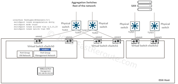
Let’s now change upstream switch configuration for the port, so frames are now tagged. This will let us introduce additional VLANs for port groups on this switch in the following sections. The configuration on the switch will be similar to the listing below:
interface TenGigabitEthernet1/0/1
  switchport trunk encapsulation dot1q
  switchport mode trunk
  switchport trunk allowed vlan 4,5,10,20
  switchport trunk native vlan 999
The configuration applied to all other switches will be following the same pattern with allowed VLAN list will change to reflect port-groups VLANs for a specific switch.
Note that unused VLAN with ID 999 is specified as native. Once this configuration is applied the connectivity to the host will be lost, as we expect VLAN 4 to be untagged. To fix this issue use DCUI: Configure Management Network > VLAN (optional) and type in VLAN ID of 4. Refer to Figure 5 which shows relevant menu screenshots. When prompted, restart management network and management connectivity will be restored.
Create vSwitch1 with WebGUI
Standard switches can be configured directly via the host, as their settings are self-contained within a single host. However, it is possible to perform configuration using vCenter too. This section will show how to create switch using direct connection first, and then how to do it via vCenter.
Create Standard Switch using ESXi host WebGUI
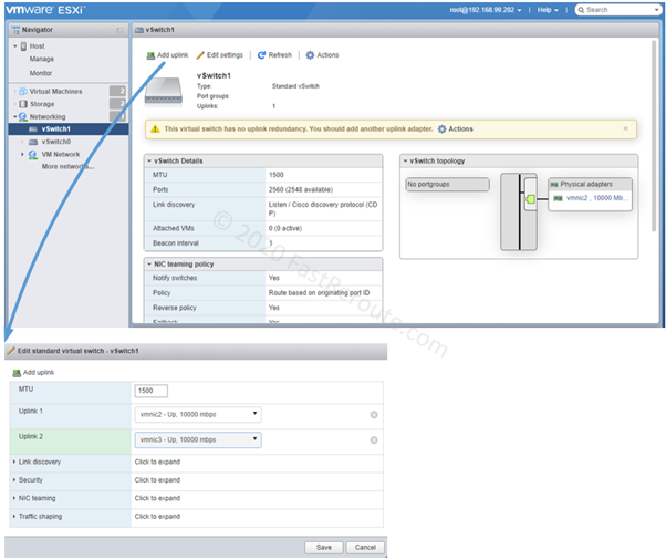
Log-in directly to the host. Click on Networking and then on the Virtual switches tab. Press Add standard virtual switch button and type-in switch name and optionally change any of the default settings.
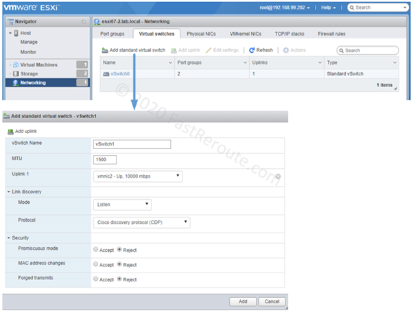
As shown in the screenshot, only a single uplink can be selected when creating a new vSwitch. To add the second uplink, click on vSwitch1 and then click on the Add uplink button. Select the correct interface opposite the “Uplink 2” label.
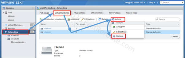
Let’s now remove the new vSwitch, so we can create it with vCenter. Click on Networking > Virtual switches > select row with vSwitch1 > click on Actions > Remove.
Create Standard Switch using vCenter host WebGUI
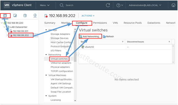
Another available option is to perform configuration via vCenter. The process is slightly different, but it achieves the same result as the direct configuration via ESXi host. Login into vCenter, Click on the desired hostname or IP address, then navigate to Configure > Networking > Virtual Switches and press Add Networking.
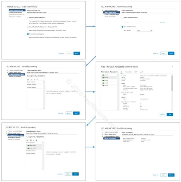
The next series of screenshots show the steps involved in creating new vSwitch. Note that the wizard combines this process with the configuration of a new VMKernel adapter, Virtual Machine Port group, or an upstream physical network adapter. As port groups will be covered in the next blog post, we will just use uplink adapter as our choice.
Note that you can add multiple uplinks at once by either pressing the “+” button several times on the third mini-screenshot below or by holding the Alt button to select multiple adapters on the fourth screen step.
Create vSwitch2 with PowerCLI
PowerCLI is a PowerShell Module provided by VMware. This how-to article provides instructions on how to install it.
As with WebGUI, it is possible to connect with PowerCLI either to ESXi host directly or to a vCenter appliance. In the examples of this section, we will connect to vCenter. The commands behave in a similar way, with the exception that we need to specify which host’s virtual switch we want to apply PowerShell cmdlets to. We will start with first connecting to the vCenter and then displaying virtual switches with the Get-VirtualSwitch command. I am using an example from command reference for Get-VirtualSwitch to perform pipe-based filtering from Get-VMHost cmdlet.
Note that we can see that there are 2 vSwitches we’ve configured in earlier sections. If you have a connection to an ESXi host, then you can just use Get-VirtualSwitch, as you will have access to a single host, so it doesn’t need to be explicitly specified.
By default, PowerShell formats the output as a table, so we cannot see all available properties. To address this, we can pipe the output with “|” character to Format-List cmdlet, which uses list-based formatting.
PowerCLI exposes certain properties that are not visible in GUI, such as a number of ports virtual switch has.
Windows PowerShell
 Copyright (C) 2016 Microsoft Corporation. All rights reserved.
 PS C:\WINDOWS\system32> Connect-VIServer 192.168.99.220
 Name                           Port  User
 ----                           ----  ----
 192.168.99.220                 443   LAB.LOCAL\Administrator
 PS C:\WINDOWS\system32> Get-VMHost -Name "192.168.99.202" | Get-VirtualSwitch
 Name                           NumPorts   Mtu   Notes
 ----                           --------   ---   -----
 vSwitch0                       2560       1500
 vSwitch1                       2560       1500
 PS C:\WINDOWS\system32> Get-VMHost -Name "192.168.99.202" | Get-VirtualSwitch | Format-List
 Id                : key-vim.host.VirtualSwitch-vSwitch0
 Key               : key-vim.host.VirtualSwitch-vSwitch0
 Name              : vSwitch0
 NumPorts          : 2560
 NumPortsAvailable : 2547
 Nic               : {vmnic0}
 Mtu               : 1500
 VMHostId          : HostSystem-host-29
 VMHost            : 192.168.99.202
 VMHostUid         : /VIServer=lab.local\administrator@192.168.99.220:443/VMHost=HostSystem-host-29/
 Uid               : /VIServer=lab.local\administrator@192.168.99.220:443/VMHost=HostSystem-host-29/VirtualSwitch=key-vim.host.VirtualSwitch-vSwitch0/
 ExtensionData     : VMware.Vim.HostVirtualSwitch
 Id                : key-vim.host.VirtualSwitch-vSwitch1
 Key               : key-vim.host.VirtualSwitch-vSwitch1
 Name              : vSwitch1
 NumPorts          : 2560
 NumPortsAvailable : 2547
 Nic               : {vmnic2, vmnic3}
 Mtu               : 1500
 VMHostId          : HostSystem-host-29
 VMHost            : 192.168.99.202
 VMHostUid         : /VIServer=lab.local\administrator@192.168.99.220:443/VMHost=HostSystem-host-29/
 Uid               : /VIServer=lab.local\administrator@192.168.99.220:443/VMHost=HostSystem-host-29/VirtualSwitch=key-vim.host.VirtualSwitch-vSwitch1/
 ExtensionData     : VMware.Vim.HostVirtualSwitch
To create a virtual switch with PowerCLI we need to use New-VirtualSwitch cmdlet. We will use the example provided in command reference to achieve this. The last command in the listing below uses –Name switch with Get-VirtualSwitch to filter the output so the only newly created switch is shown.
PS C:\WINDOWS\system32> Get-VMHost -Name "192.168.99.202" | New-VirtualSwitch -Name "vSwitch2" -Nic vmnic4,vmnic5
Name                           NumPorts   Mtu   Notes
----                           --------   ---   -----
vSwitch2                       2560       1500
PS C:\WINDOWS\system32> Get-VMHost -Name "192.168.99.202" | Get-VirtualSwitch
Name                           NumPorts   Mtu   Notes
----                           --------   ---   -----
vSwitch0                       2560       1500
vSwitch1                       2560       1500
vSwitch2                       2560       1500
PS C:\WINDOWS\system32> Get-VMHost -Name "192.168.99.202" | Get-VirtualSwitch -Name "vSwitch2" | Format-List
Id                : key-vim.host.VirtualSwitch-vSwitch2
Key               : key-vim.host.VirtualSwitch-vSwitch2
Name              : vSwitch2
NumPorts          : 2560
NumPortsAvailable : 2544
Nic               : {vmnic4, vmnic5}
Mtu               : 1500
VMHostId          : HostSystem-host-29
VMHost            : 192.168.99.202
VMHostUid         : /VIServer=lab.local\administrator@192.168.99.220:443/VMHost=HostSystem-host-29/
Uid               : /VIServer=lab.local\administrator@192.168.99.220:443/VMHost=HostSystem-host-29/VirtualSwitch=key-vim.host.VirtualSwitch-vSwitch2/
ExtensionData     : VMware.Vim.HostVirtualSwitch
Now we have almost achieved the desired target topology with the exception of the second physical adapter attached to vSwitch0. The cmdlet name performing this operation is Add-VirtualSwitchPhysicalNetworkAdapter and we are using modified example 2 from the command reference.
Note how variables are used to store an object returned by Get-* cmdlets. They must start with the dollar sign “$”. We then can use these variables as parameters in other cmdlets.
 PS C:\WINDOWS\system32> $VariableSwitch01 = Get-VMHost -Name "192.168.99.202" | Get-VirtualSwitch -Name "vSwitch0"
 PS C:\WINDOWS\system32> $VariableAdapter01 = Get-VMHost -Name "192.168.99.202" | Get-VMHostNetworkAdapter -Physical -Name vmnic1
 PS C:\WINDOWS\system32> Add-VirtualSwitchPhysicalNetworkAdapter -VirtualSwitch $VariableSwitch01 -VMHostPhysicalNic $VariableAdapter01
 Confirm
 Are you sure you want to perform this action?
 Performing the operation "Adding physical network adapter(s) 'vmnic1'" on target "vSwitch0".
 [Y] Yes  [A] Yes to All  [N] No  [L] No to All  [S] Suspend  [?] Help (default is "Y"): y
 PS C:\WINDOWS\system32> Get-VMHost -Name "192.168.99.202" | Get-VirtualSwitch -Name "vSwitch0" | Format-List
 Id                : key-vim.host.VirtualSwitch-vSwitch0
 Key               : key-vim.host.VirtualSwitch-vSwitch0
 Name              : vSwitch0
 NumPorts          : 2560
 NumPortsAvailable : 2543
 Nic               : {vmnic0, vmnic1}
 Mtu               : 1500
 VMHostId          : HostSystem-host-29
 VMHost            : 192.168.99.202
 VMHostUid         : /VIServer=lab.local\administrator@192.168.99.220:443/VMHost=HostSystem-host-29/
 Uid               : /VIServer=lab.local\administrator@192.168.99.220:443/VMHost=HostSystem-host-29/VirtualSwitch=key-vim.host.VirtualSwitch-vSwitch0/
 ExtensionData     : VMware.Vim.HostVirtualSwitch
In the next article, we will continue the configuration of our topology.