vSphere ESXi Networking Guide – Part 3: Standard Switches Configuration ESXi 6.7
This is the third part of the vSphere ESXi Networking Guide. In the previous post, we’ve created three virtual switches and assigned uplink ports to them. In this post we will add port groups and VMKernel ports to the vSwitches. The examples in this article are based on the ESXi version 6.7.
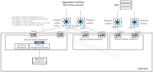
The start state for this article is shown in Figure 1.
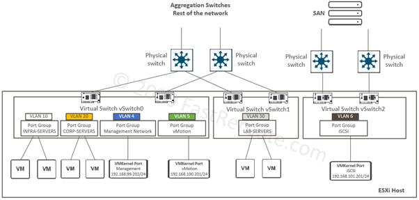
This post’s configuration examples will bring the state of the virtual network to the one displayed in Figure 2, as shown below.
VM Port Group Tasks
The article’s examples will follow the same pattern we’ve used in the previous post – first we will use the WebGUI configuration of ESXi host and vCenter. And then PowerCLI configuration will be demonstrated.
ESXi Host Based Configuration
The first task is the addition of the INFRA-SERVERS port group. It is mapped to VLAN 10, as shown in Figure 2. With web browser navigate to IP address or full domain name of ESXi host and login with ESXi local credentials.
Click on the Networking navigation menu, then on Port groups tab, and press the “Add port group” button.
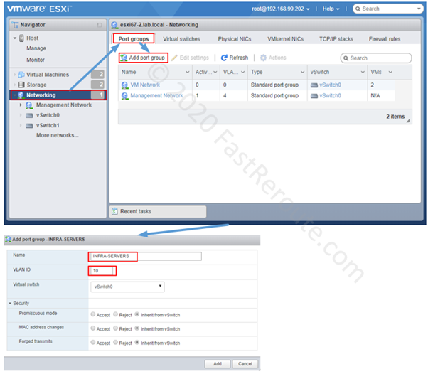
As shown in Figure 3, enter the port group name, the VLAN ID and select the virtual switch. Let’s accept default security settings which are inheriting configuration done on the vSwitch level.
vCenter Based Configuration
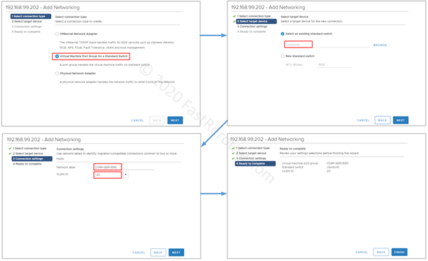
We will use the vCenter Web GUI to add the second port group called CORP-SERVERS mapped to VLAN 20. Firstly click on Hosts and Cluster icon, then select the IP address of VM host. Click on the Configure tab, then select Virtual switches on the menu on the left and then click Add Networking button.
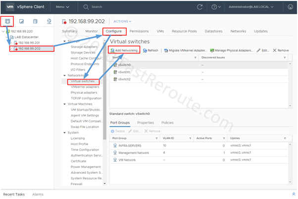
Select “Virtual Machine Port Group for a Standard Switch” as a connection type. Then choose the virtual standard switch. In the screenshot below, the default option of vSwitch0 is selected. Then specify “CORP-SERVERS” as the port group name and 20 as VLAN ID. Review the summary and press Finish.
PowerCLI Configuration
In this section, we will create a “LAB-SERVERS” port group as part of the vSwitch1. The port group is assigned a VLAN ID of 30, as shown in the target state diagram.
The first two cmdlets connect to vCenter and store the virtual switch object in a variable called $VariableSwitch01, which we will use in the next commands to specify the parent switch for the “LAB-SERVERS” port group. This is similar to the examples we used in the previous article.
 PS C:\WINDOWS\system32> Connect-VIServer 192.168.99.220
 Name                           Port  User
 ----                           ----  ----
 192.168.99.220                 443   LAB.LOCAL\Administrator
 PS C:\WINDOWS\system32> $VariableSwitch01 = Get-VMhost -Name "192.168.99.202" | Get-VirtualSwitch -Name "vSwitch1"
New cmdlets we will be using in the example below are New-VirtualPortGroup and Get-VirtualPortGroup.
PS C:\WINDOWS\system32> New-VirtualPortGroup -VirtualSwitch $VariableSwitch01 -Name "LAB-SERVERS" -VLanId 30
 Name                      Key                            VLanId PortBinding NumPorts
 ----                      ---                            ------ ----------- --------
 LAB-SERVERS               key-vim.host.PortGroup-LAB-… 30
 PS C:\WINDOWS\system32> Get-VirtualPortGroup -VirtualSwitch $VariableSwitch01
 Name                      Key                            VLanId PortBinding NumPorts
 ----                      ---                            ------ ----------- --------
 LAB-SERVERS               key-vim.host.PortGroup-LAB-… 30
 PS C:\WINDOWS\system32> Get-VirtualPortGroup -VirtualSwitch $VariableSwitch01 | Format-List
 Name              : LAB-SERVERS
 VirtualSwitchId   : key-vim.host.VirtualSwitch-vSwitch1
 VirtualSwitchUid  : /VIServer=lab.local\administrator@192.168.99.220:443/VMHost=HostSystem-host-29/VirtualSwitch=key-vim.host.VirtualSwitch-vSwitch1/
 VirtualSwitch     : vSwitch1
 Key               : key-vim.host.PortGroup-LAB-SERVERS
 Port              :
 VLanId            : 30
 VirtualSwitchName : vSwitch1
 VMHostId          : HostSystem-host-29
 VMHostUid         : /VIServer=lab.local\administrator@192.168.99.220:443/VMHost=HostSystem-host-29/
 Uid               : /VIServer=lab.local\administrator@192.168.99.220:443/VMHost=HostSystem-host-29/VirtualSwitch=key-vim.host.VirtualSwitch-vSwitch1/VirtualPortGroup=key-vim.host.PortGroup-LAB-SERVERS/
 ExtensionData     : VMware.Vim.HostPortGroup
To demonstrate how to delete a port group we will remove the default port group “VM Network” that was automatically created during ESXi host installation. Remove-VirtualPortGroup cmdlet is used to perform the operation.
The first line of the listing below is similar to the one we used in the example above but uses another variable name. It stores the virtual switch named “vSwitch0” on ESXi host 192.168.99.202 as a variable. The second line stores the port group named “VM Network” in another variable. Then we use Remove-VirtualPortGroup cmdlet to delete the port group.
 PS C:\WINDOWS\system32> $VariableSwitch00 = Get-VMhost -Name "192.168.99.202" | Get-VirtualSwitch -Name "vSwitch0"
 PS C:\WINDOWS\system32> $VariablePortGroup = Get-VirtualPortGroup -VirtualSwitch $VariableSwitch00 -Name "VM Network"
 PS C:\WINDOWS\system32> Remove-VirtualPortGroup $VariablePortGroup
 Perform operation?
 Perform operation 'Remove virtual port group.' on 'LAB-SERVERS'.
 [Y] Yes  [A] Yes to All  [N] No  [L] No to All  [S] Suspend  [?] Help (default is "Y"): y
VMs Interface Configuration
Now we have the required infrastructure prepared for connecting VM’s virtual adapters to port groups. Let’s start with the ESXi Host-Based configuration.
ESXi Host Based Configuration
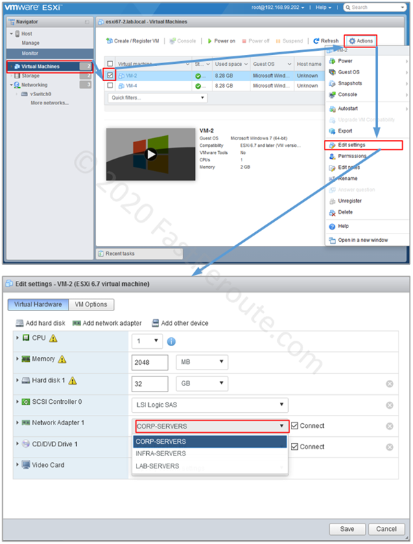
Log in into ESXi host, press on the Virtual Machines menu and then click on the checkbox next to the VM that will be configured.
Click on the Actions menu button and select the “Edit settings” option. Now we can move VM’s network adapter to the required port group.
The next section shows how to perform the same configuration using the vCenter WebGUI interface.
vCenter Based Configuration
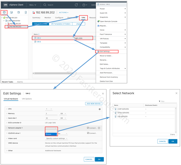
Log in into vCenter and click on the ESXi hostname or IP address, then click on the VM tab. Right-click on the VM’s row and select Edit Settings. Click on the drop-down box next to the network adapter and select Browse. In the list of available networks select one of the port groups.
PowerCLI Configuration
To perform configuration using PowerCLI we first need to locate the correct VM using Get-VM cmdlet and then either saving it as variable or piping it to Get-NetworkAdapter cmdlet we will be able to get access to its network adapter. Then Set-NetworkAdapter can be used to connect the network adapter to the correct port group. We will locate port group via virtual switch, as demonstrated in the previous example.
Let’s first refer to the diagram explaining how commands components are related and then check the command listing. Figure 8 shows the variables and cmdlets used in this example. The cmdlet that performs the required configuration is Set-NetworkAdapter. As per the command reference, we need to specify two pieces of information to change the adapter’s port group:
- Adapter that we want to move
- Port group that will be hosting the adapter
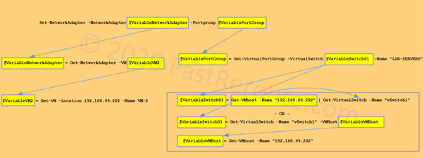
The diagram shows how to get access to these objects by running commands from the bottom to the top. Note that there are two different ways of how $VariableSwitch01 can be defined – with and without pipe operator ‘|’.
Full listing of the commands is provided in the sample below:
PS C:\WINDOWS\system32> Connect-VIServer 192.168.99.220
 Name                           Port  User
 ----                           ----  ----
 192.168.99.220                 443   LAB.LOCAL\Administrator
 PS C:\WINDOWS\system32> Get-VM -Location 192.168.99.202
 Name                 PowerState Num CPUs MemoryGB
 ----                 ---------- -------- --------
 VM-4                 PoweredOff 1        2.000
 VM-2                 PoweredOff 1        2.000
 PS C:\WINDOWS\system32> $VariableVM2 = Get-VM -Location 192.168.99.202 -Name VM-2
 PS C:\WINDOWS\system32> $VariableNetworkAdapter = Get-NetworkAdapter -VM $VariableVM2
 PS C:\WINDOWS\system32> $VariableNetworkAdapter | Format-List
 MacAddress       : 00:50:56:91:e3:e5
 WakeOnLanEnabled : True
 NetworkName      : VM Network
 Type             : e1000
 ParentId         : VirtualMachine-vm-85
 Parent           : VM-2
 Uid              : /VIServer=lab.local\administrator@192.168.99.220:443/VirtualMachine=VirtualMachine-vm-85/NetworkAdapter=4000/
 ConnectionState  : NotConnected, GuestControl, StartConnected
 ExtensionData    : VMware.Vim.VirtualE1000
 Id               : VirtualMachine-vm-85/4000
 Name             : Network adapter 1
 PS C:\WINDOWS\system32> $VariableSwitch01 = Get-VMhost -Name "192.168.99.202" | Get-VirtualSwitch -Name "vSwitch1"
 PS C:\WINDOWS\system32> $VariablePortGroup = Get-VirtualPortGroup -VirtualSwitch $VariableSwitch01 -Name "LAB-SERVERS"
 PS C:\WINDOWS\system32> Set-NetworkAdapter -NetworkAdapter $VariableNetworkAdapter -Portgroup $VariablePortGroup
 Confirm
 Are you sure you want to perform this action?
 Performing the operation "Connect to portgroup" on target "Network adapter 1".
 [Y] Yes  [A] Yes to All  [N] No  [L] No to All  [S] Suspend  [?] Help (default is "Y"): y
 Name                 Type       NetworkName  MacAddress         WakeOnLan
                                                                   Enabled
 ----                 ----       -----------  ----------         ---------
 Network adapter 1    e1000      LAB-SERVERS  00:50:56:91:e3:e5       True
VMKernel Port Configuration
The next step in this article is the configuration of the VMKernel ports. These ports are used to provide communication to the ESXi host itself. The first example is based on WebGUI of the ESXi host to create a VMKernel adapter for VMotion.
ESXi Host Based Configuration
Log in into the ESXi host and then click on the “Networking” option on the side menu, then select VMKernel NICs and press the “Add VMKernel NIC” button. On the pop-up menu fill-in the port group details, the vSwitch and the VLAN ID.
It is recommended to use the “New port group” option, as VMKernel requires a dedicated port group that cannot be shared with the VM ports. Placing a VMKernel port into the existing port group with VM ports attached will cause these ports to be moved out of the port group with a probability of causing downtime.
vMotion stack is available by default, so we will select it from the list of the TCP/IP stacks. Note that the TCP/IP stack cannot be changed after the VMKernel adapter is created.
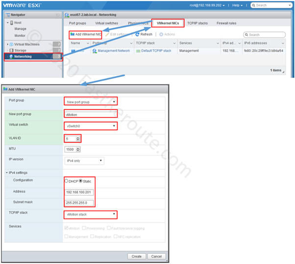
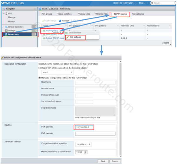
The static IP address of 192.168.100.201/24 is specified. Note that there is no default gateway configuration available under the VMKernel NIC. To configure it change the settings of vMotion stack as shown in the next screenshot.
To perform this configuration, click on the TCP/IP stacks tab and then right-click on vMotion stack and select the “Edit settings” option in the context menu invoked by the right-click. Adjust the IPv4 gateway setting. Note that the option can be modified only if there is a VMKernel adapter associated with the port group.
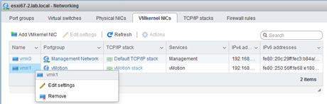
Let’s now delete VMKernel NIC by right-clicking on it and selecting the “Remove” option, so we can perform the same procedure using the vCenter interface.
vCenter Based Configuration
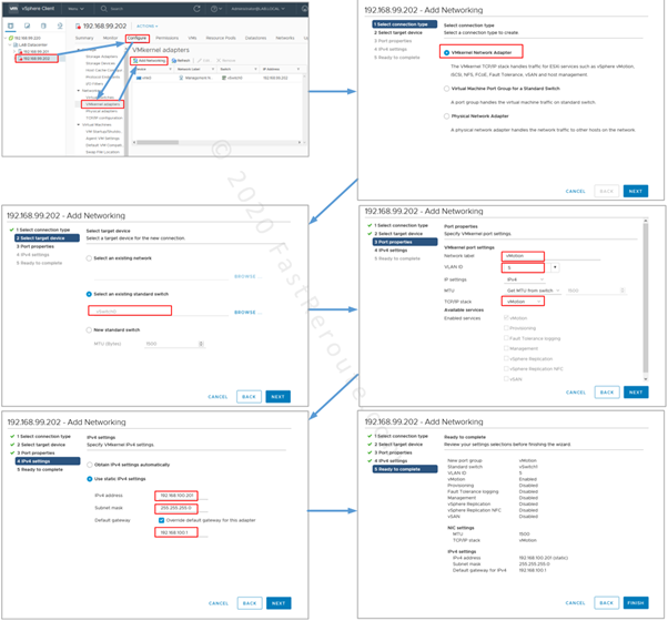
Log in into vCenter and click on the ESXi hostname or IP address, then select the Configure tab. Chose the “VMKernel adapters” option in the host’s menu and then press the “Add Networking” button. This will launch the familiar “Add Networking” configuration wizard. This time select VMKernel Network Adapter, select vSwitch0 and fill in the port group settings. Note that there is an option to override the TCP/IP stack default gateway with “User static IPv4 settings”. This default gateway will not appear in the TCP/IP stack routing table.
PowerCLI Configuration
To create an iSCSI VMKernel adapter with PowerCLI we will use New-VMHostNetworkAdapter cmdlet. After logging into vCenter let’s save vSwitch 2 as a variable.
Then a VMKernel adapter in a new PortGroup named iSCSI within vSwitch 2 is created. The VMKernel port’s IP address is set to 192.168.101.201. Get-VMHostNetworkAdapter cmdlet shows the settings of a newly created VMKernel interface. Finally, we will move the port group to the correct VLAN.
PS C:\WINDOWS\system32> Connect-VIServer 192.168.99.220
 Name                           Port  User
 ----                           ----  ----
 192.168.99.220                 443   LAB.LOCAL\Administrator
 PS C:\WINDOWS\system32> $VariableSwitch02 = Get-VMhost -Name "192.168.99.202" | Get-VirtualSwitch -Name "vSwitch2"
 PS C:\WINDOWS\system32> New-VMHostNetworkAdapter -VirtualSwitch $VariableSwitch02 -PortGroup "iSCSI" -IP 192.168.101.201  -SubnetMask 255.255.255.0
 Name       Mac               DhcpEnabled IP              SubnetMask      DeviceName
 ----       ---               ----------- --              ----------      ----------
 vmk2       00:50:56:6e:69:2a False       192.168.101.201 255.255.255.0         vmk2
 PS C:\WINDOWS\system32> Get-VMHostNetworkAdapter -VirtualSwitch $VariableSwitch02 -Name vmk2 | Format-List
 VMotionEnabled               : False
 FaultToleranceLoggingEnabled : False
 ManagementTrafficEnabled     : False
 IPv6                         : {fe80::250:56ff:fe6e:692a/64}
 AutomaticIPv6                : False
 IPv6ThroughDhcp              : False
 IPv6Enabled                  : False
 Mtu                          : 1500
 VsanTrafficEnabled           : False
 PortGroupName                : iSCSI
 Id                           : key-vim.host.VirtualNic-vmk2
 VMHostId                     : HostSystem-host-29
 VMHost                       : 192.168.99.202
 VMHostUid                    : /VIServer=lab.local\administrator@192.168.99.220:443/VMHost=HostSystem-host-29/
 DeviceName                   : vmk2
 Mac                          : 00:50:56:6e:69:2a
 DhcpEnabled                  : False
 IP                           : 192.168.101.201
 SubnetMask                   : 255.255.255.0
 Uid                          : /VIServer=lab.local\administrator@192.168.99.220:443/VMHost=HostSystem-host-29/HostVMKernelVirtualNic=key-vim.host.VirtualNic-vmk2/
 Name                         : vmk2
 ExtensionData                : VMware.Vim.HostVirtualNic
 PS C:\WINDOWS\system32> $VariablePortGroup = Get-VirtualPortGroup -Name "iSCSI"
 PS C:\WINDOWS\system32> Set-VirtualPortGroup -VirtualPortGroup $VariablePortGroup -VLanId 6
 Name                      Key                            VLanId PortBinding NumPorts
 ----                      ---                            ------ ----------- --------
 iSCSI                     key-vim.host.PortGroup-iSCSI   6
Load Balancing and Security Parameters
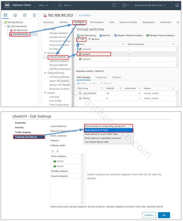
Let’s consider an example when we want to enable per-packet load balancing for vSwitch 1. This will affect LAB-SERVERS and vMotion port groups, as, by default, port groups inherit configuration defined on a vSwitch.
As shown in the first article of this series, per-packet load balancing requires the upstream switch (or switches in some scenarios) to use static link aggregation. As our switches are not physically or virtually stacked we will need to move both links to the same switch for this example to work properly. Otherwise, switches will have to rapidly flush and re-learn VM’s MAC address with frames sent by VM host over different uplinks as the result of load balancing. This will degrade the network performance and produce multiple MAC flapping alerts in the logs.
To perform configuration using vCenter, select the host, then press on the Configure tab, select Virtual switches. Then click on the vSwitch1 and press the Edit button. In the “Edit Settings” pop-up window select the “Teaming and failover” menu on the left and then choose the “Route based on IP hash” option as the load balancing mechanism.
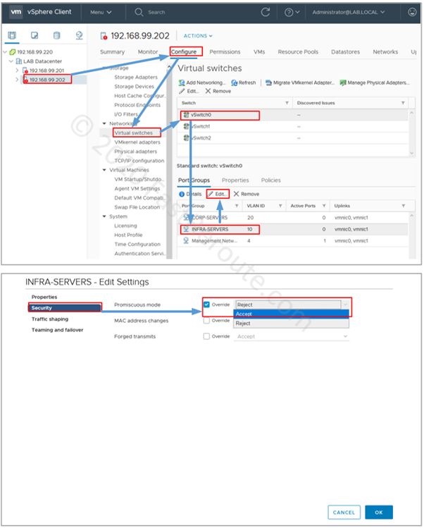
For the next example, assume that we’ve been instructed to send a copy of all traffic received on vSwitch0 to the INFRA-SERVERS port group, so this traffic can be captured with Wireshark for some troubleshooting. The setting that we need to enable is Promiscuous mode.
We know that the correct approach for this task is to create a new port group with a single server that runs Wireshark, however, to make this example more focused on the task we will enable this setting for the existing port group. Refer to the first section of this blog post on how to create a new port group for the production environment.
We will use vCenter for this configuration. Navigate to Virtual switches in WebGUI, then select vSwitch0, as it contains the INFRA-SERVERS port group. Select the port group and press the Edit button.
In the configuration pop-up window, click on the Security menu and enable the override checkbox next to Promiscuous mode and select Accept.
Conclusion
This is the final article in the VMWare standard switch series (see part 1 and part 2) and I hope that it is helpful in getting familiar with how standards switches operate and configured.