Cisco SD-WAN Templates Step by Step
The procedure described in this article can be used as part of the bootstrap process of Cisco IOS-XE devices. We start with a CSR1000V SD-WAN edge router in CLI mode, registered with vManage.
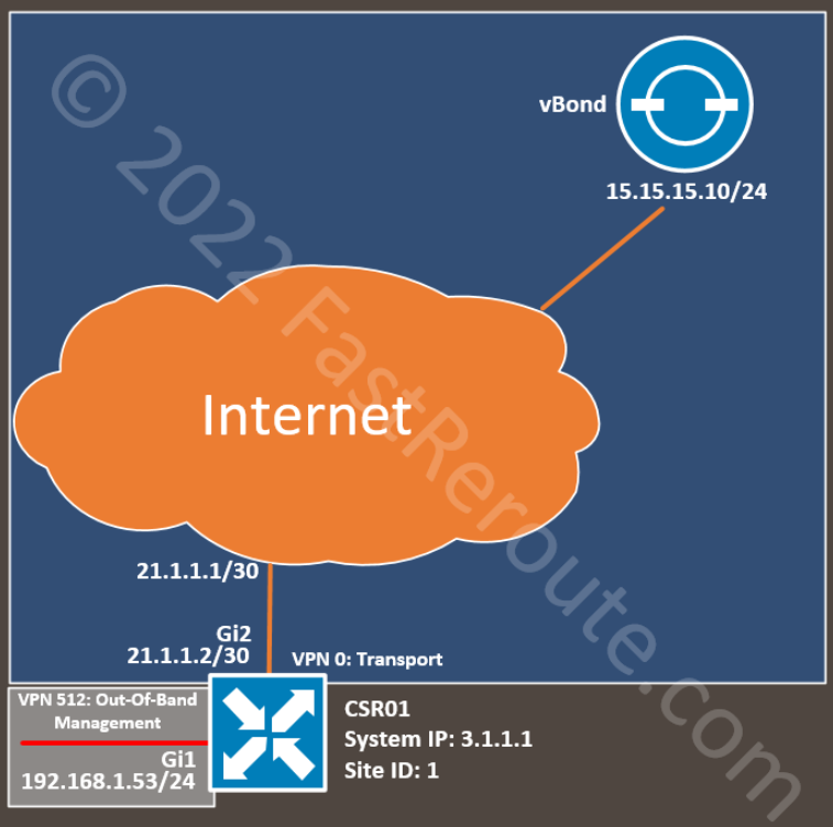
The topology has a single router connected to the Internet via an Ethernet interface. We configured the IP address on this interface and the default static route statically.
The configuration includes an out-of-band management interface, so we are not limited to console connectivity for troubleshooting and can use SSH over the Ethernet interface. This part of the configuration is optional, and you can skip the templates for out-of-band VPN 512.
See the router’s basic CLI configuration in the listing below. We will substitute it with generated configuration from the feature and device templates while ensuring that the device is still able to connect to vManage.
We don’t use the service-side (LAN) configuration in this example. Additional templates can enable other settings after the device is switched to template-based management.
Base CLI Configuration
The basic configuration of the SD-WAN edge device includes the following details:
- System parameters (lines 3-10)
- Transport and tunnel interface configuration (lines 25-33, 41-45)
- Transport VPN routing (line 35)
- Out-Of-Band Management VPN and Interface (optional, lines 12-23)
config-transaction
!
system
 system-ip             3.1.1.1
 site-id               1
 admin-tech-on-failure
 organization-name     SD-WAN-TESTLAB
 vbond 100.1.1.51
!
hostname CSR01
!
vrf definition Mgmt-intf
 rd 1:512
 !
 address-family ipv4
  route-target export 1:512
  route-target import 1:512
 exit-address-family
exit
!
interface GigabitEthernet1
 vrf forwarding Mgmt-intf
 ip address 192.168.1.53 255.255.255.0
!
interface GigabitEthernet2
 no shutdown
 ip address 21.1.1.2 255.255.255.252
!
interface Tunnel0
 no shutdown
 ip unnumbered GigabitEthernet2
 tunnel source GigabitEthernet2
 tunnel mode sdwan
!
ip route 0.0.0.0 0.0.0.0 21.1.1.1
!
line vty 0 4
 transport input ssh
!
sdwan
 interface GigabitEthernet2
  tunnel-interface
   encapsulation ipsec
   color default
  exit
 exit
!
commit
Feature templates
In this article, we will create all feature templates from scratch.
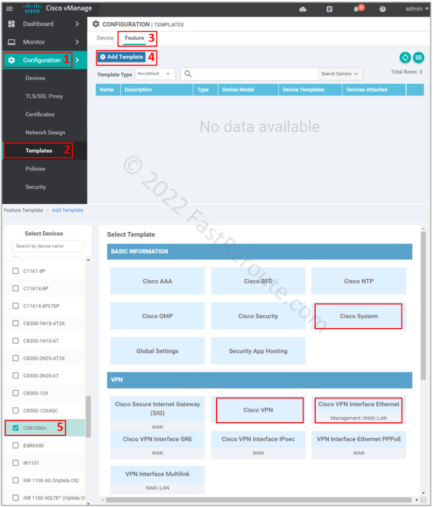
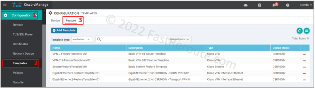
To add a feature template refer to the screenshot below.
Start by selecting Configuration > Templates in the side menu. Then click on the Feature tab and the “Add Template” button. Select CSR1000v as the device type. I highlighted the templates used in this article – System, VPN, and Ethernet.
Step 1. System template configuration
This template defines System IP, Site ID, and Hostname details. We want to generate the following configuration with the template:
system
 system-ip             3.1.1.1
 site-id               1
 admin-tech-on-failure
 organization-name     SD-WAN-TESTLAB
 vbond 100.1.1.51
!
hostname CSR01
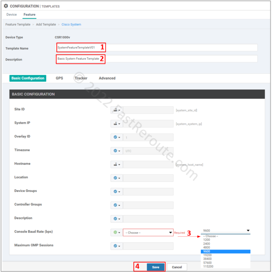
To add a System template select the “Cisco System” button in the “Add Template” window shown in Figure 2. Set the name and description of the template.
Default options have variables defined for the parameters we want to define. The only mandatory setting is the Console Baud Rate, and figure 3 shows the required details.
Step 2. Transport VPN
This template defines transport VPN, a global routing context (VRF 0) in Cisco IOS-XE. With this template, we aim to generate the static default route from the complete configuration:
ip route 0.0.0.0 0.0.0.0 21.1.1.1
To add it click on the “Cisco VPN” button on the add feature template page, shown in Figure 2. Add name and description of the template.
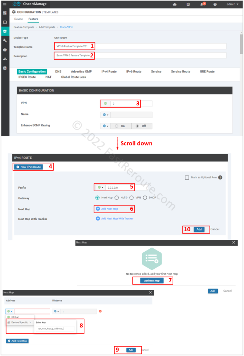
Set VPN value of 0, which is reserved ID for transport VPN.
For our configuration, we need only specify a default route. To be able to re-use template, use a device variable for the next hop (vpn_next_hop_ip_address_0). This variable can be either the IP address of the next-hop or interface name for point-to-point connections.
Don’t forget to press Add button (#10), as the configuration window will not warn you that the route is not added, which will cause the device to lose connectivity to vManage. Not saving sub-configuration sections is a common issue, which can happen across many vManage configuration pages, as the Web user interface doesn’t force a user to save or discard when adding sub-elements.
Step 3. Transport interface
This template generates the configuration shown below:
interface GigabitEthernet2
 no shutdown
 ip address 21.1.1.2 255.255.255.252
!
interface Tunnel0
 no shutdown
 ip unnumbered GigabitEthernet2
 tunnel source GigabitEthernet2
 tunnel mode sdwan
!
sdwan
 interface GigabitEthernet2
  tunnel-interface
   encapsulation ipsec
   color default
  exit
 exit
Use procedure from the first section to get to the Feature template selection (Figure 2) and then select “Cisco VPN Interface Ethernet” as the type.
Specify the template name and description. Change the following values:
- Shutdown – No
- Interface name – GigabitEthernet2
- IPv4 Address/prefix-length – variable (ge2_if_ipv4_address)
- Tunnel Interface – On
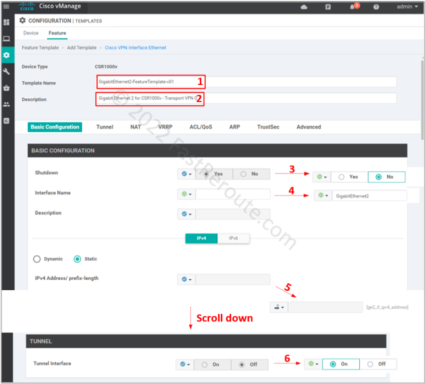
Save the template.
Step 4. Out-of-band management (optional)
This section configures templates that will generate the following commands:
vrf definition Mgmt-intf
rd 1:512
!
address-family ipv4
route-target export 1:512
route-target import 1:512
exit-address-family
exit
!
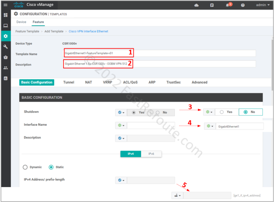
interface GigabitEthernet1
vrf forwarding Mgmt-intf
ip address 192.168.1.53 255.255.255.0
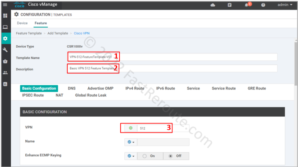
This configuration is similar to the previous two steps. The management VPN uses a reserved ID of 512. SD-WAN overlay doesn’t transport it over, which is why it is called out-of-band. You can only access it locally or expand it using a dedicated network.
In this example, we don’t set up any static routes in VPN 512, as we plan to connect to the device locally via port GigabitEthernet1. In your network, you can set up static routes without any risk to the transport or other VPNs, as each VPN is a VRF, which has its isolated routing table.
The interface configuration differs from the transport interface by not having the tunnel option enabled.
Step 5. Configure device template
We have created five feature templates, as shown in Figure 8.
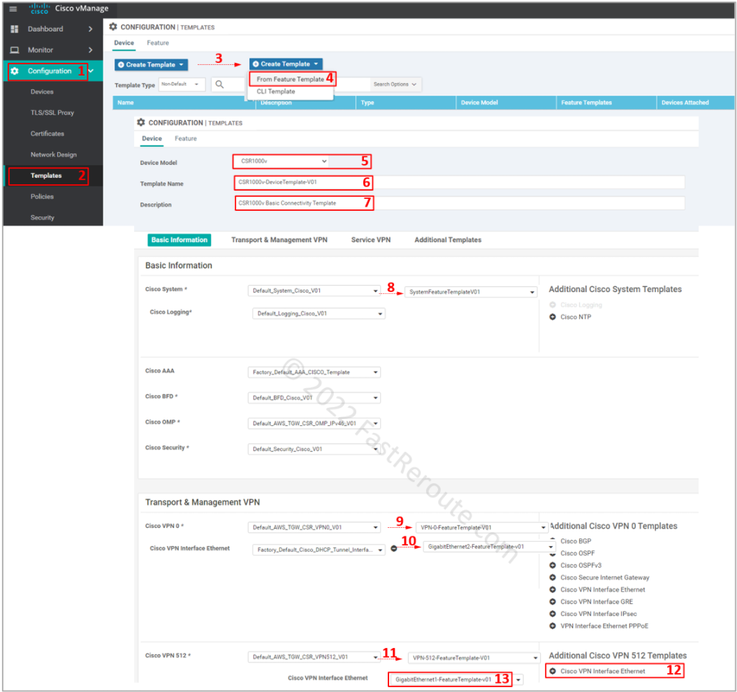
Let’s create a device template using the steps shown in Figure 9. Select device type, then provide a name and description for the template. Change the following templates:
- Cisco System
- Cisco VPN 0
- Cisco VPN Interface Ethernet
- Cisco VPN 512
- Cisco VPN Interface Ethernet (add it first)
Cisco AAA template defines user authentication for out-of-band management access. The pre-configured AAA template defines default credentials – user/password combination of admin/admin. Use them to SSH to the device via VPN 512.
You should change it in the production network as a security precaution by defining a custom Cisco AAA template. Save the device template.
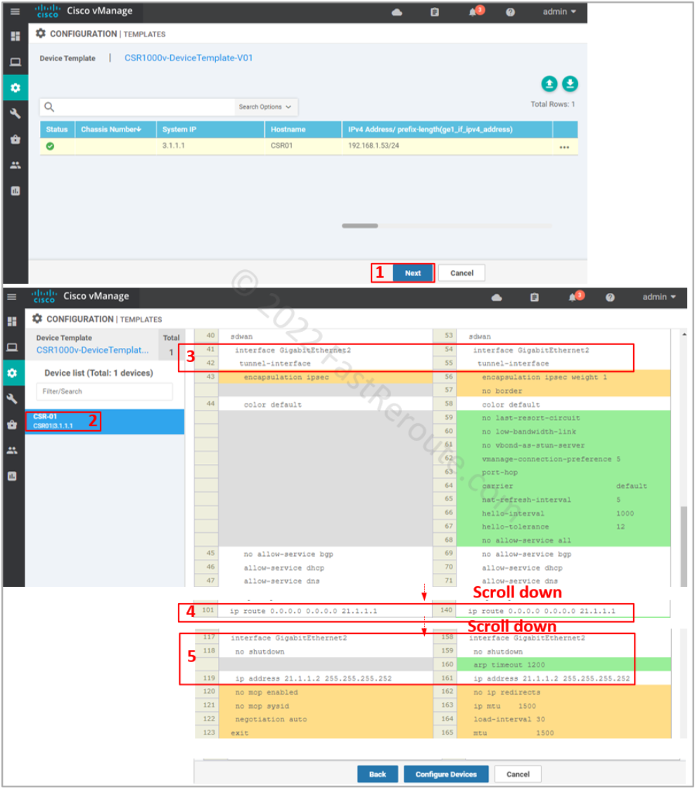
Step 6. Apply device template
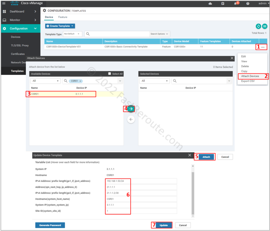
Now it’s time to apply the template to the device. Open the template configuration page select the device template created in the previous step. Click on the three dots column and then on Attach Devices.
Select CSR01, click on the right-pointing arrow, and then the Attach button.
Fill in values for the variables, which came from the templates defined earlier, and press Update.
List of variables and their values:
- ge1_if_ipv4_address – 192.168.1.53/24
- vpn_next_hop_ip_address_0 – 21.1.1.1
- ge2_if_ipv4_address – 21.1.1.2/30
- system_host_name – CSR01
- system_system_ip – 3.1.1.1
- system_site_id – 1
The final step is to check the configuration changes in CLI, as shown in Figure 11. Check the transport interface and VPN 0 static route.