Cisco SD-WAN Firewall Step-by-step
In this blog post, we want to show how to enable a zone-based firewall on the Cisco SD-WAN platform. The example continues on the topology in the Direct Internet Access article. We introduced an additional site to demonstrate that the configuration applied doesn’t affect inter-site traffic.
The diagram below shows the topology with a PC behind CSR1. It can access the Internet without any restrictions after enabling Direct Internet Access. If we want to restrict what is reachable from the service side, two options are available – access lists attached to the internal interface and zone-based firewall functionality. As on the traditional, non-SD-WAN router, access-lists are used in scenarios when no stateful inspection is required, for example, when you want to drop RFC 1918 traffic coming from your guest WIFI segment. Cisco zone-based firewall adds the ability to identify the application and stateful inspection, which allows return traffic if it’s part of the permitted session.
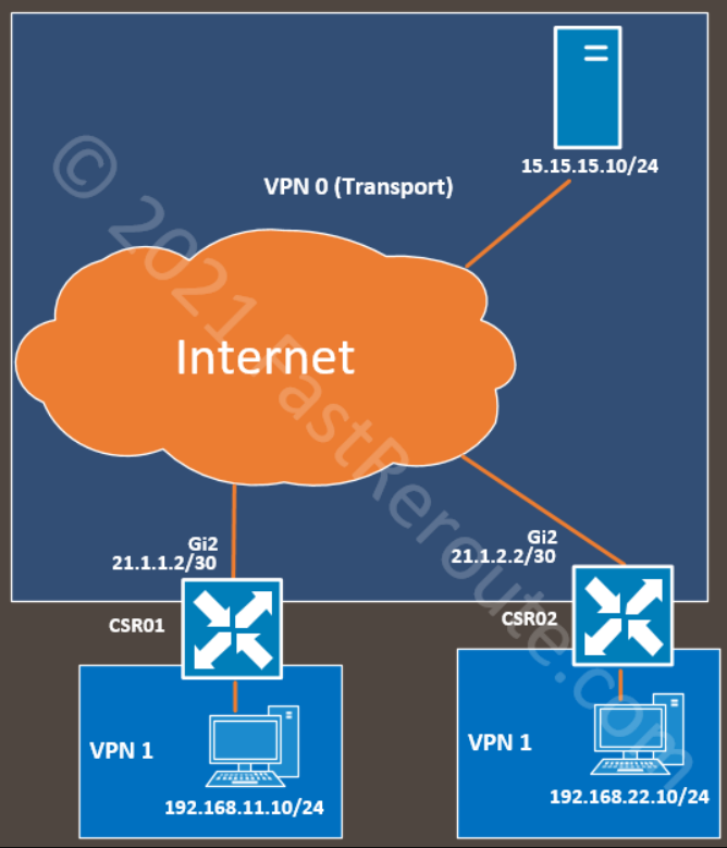
Initial setup for DIA blocking all outbound traffic
The first section will create and associate a security policy that will block all traffic from the internal network to the Internet.
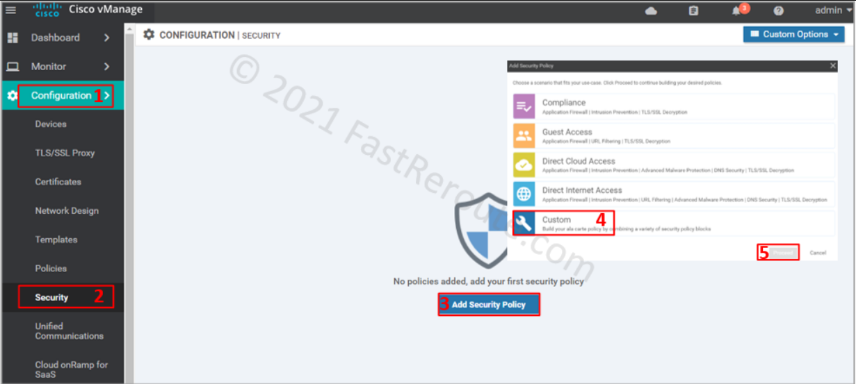
To apply the firewall rules, use a localized security policy. Navigate to Configuration > Policy. Click on Add Security Policy. Choose a custom policy from the list below, as this option shows all possible configuration elements.
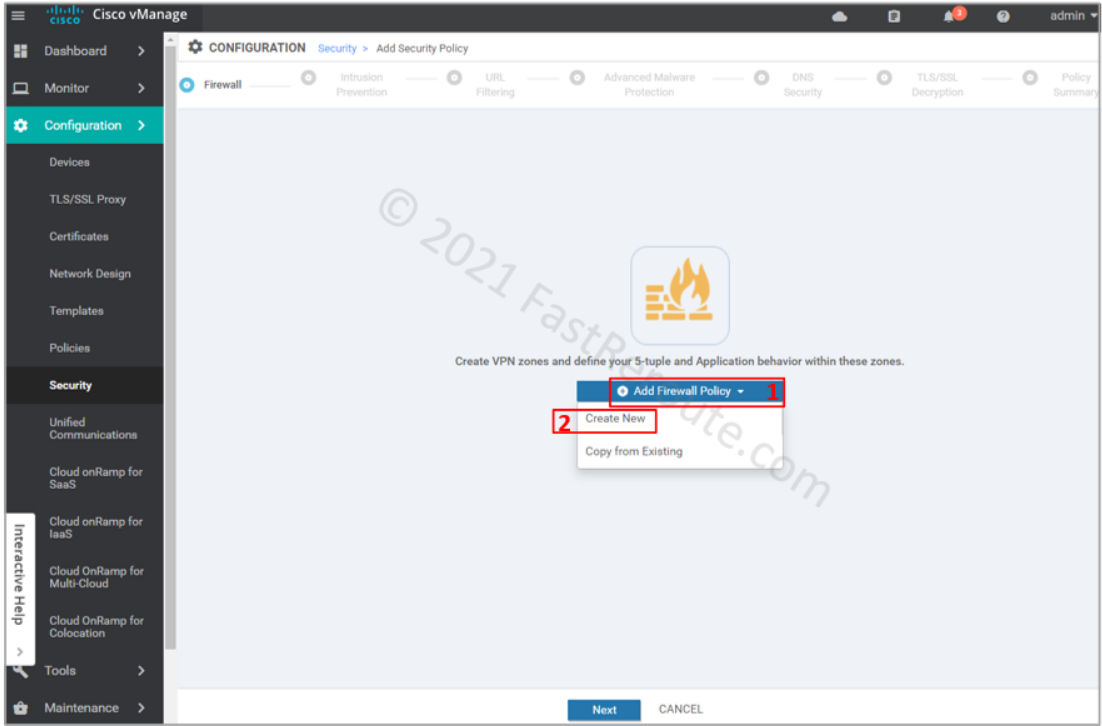
The first screen in the wizard is firewall configuration. Click on Add Firewall Policy, and then on Create New.
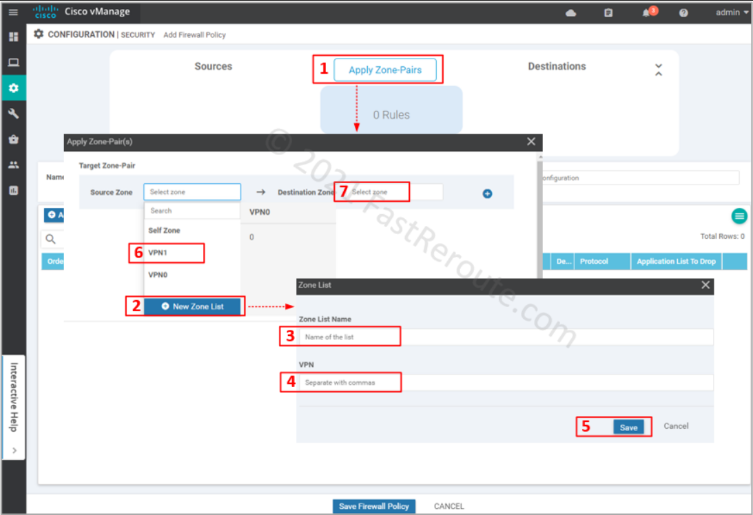
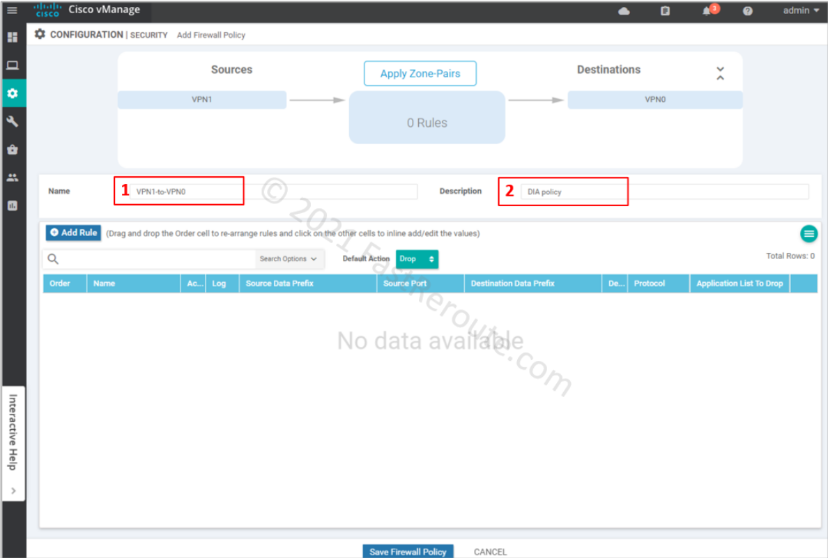
Define source and destination zone pairs by clicking on Apply Zone-Pairs button. Select source and destination zones. You can create zones within the wizard by specifying which VPNs will be part of them.
Provide Name and Description for the firewall policy. We can add rules as required; however, we want to drop all the traffic first. The default action, which is applied when no rules match the packet, is Drop (you can change this behavior by selecting Pass in the dropdown menu).
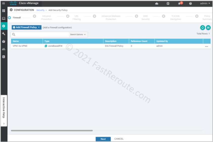
Review created firewall policy and press Next.
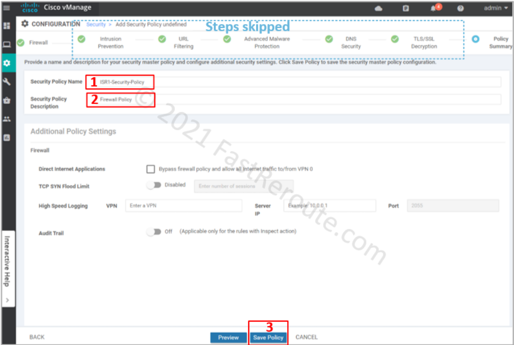
We’ve clicked through all remaining pages of the wizard without adding any configuration. On the “Policy summary” page, provide Security Policy Name and its description.
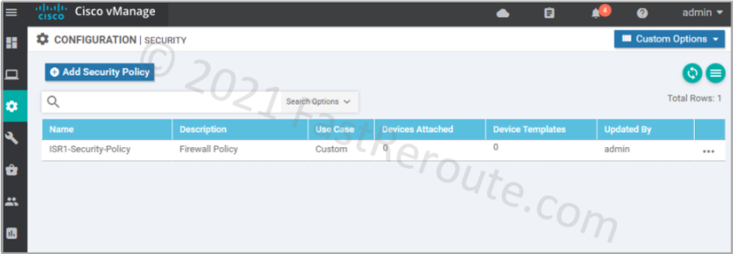
After clicking on the Save Policy button, we can see the policy we’ve just created in the list.
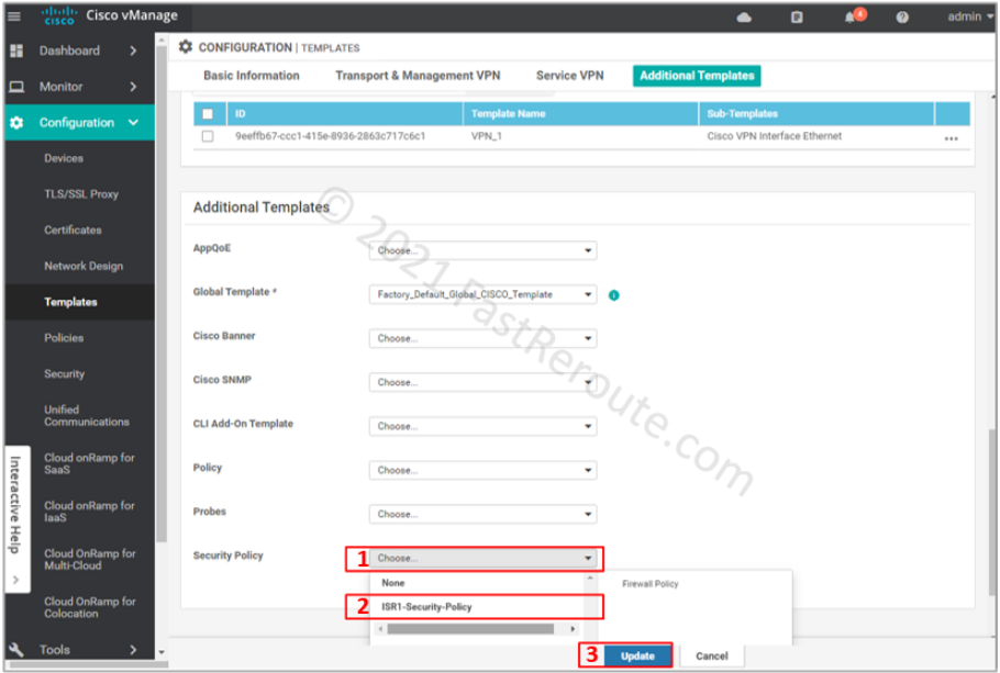
Now it’s time to apply the policy to the device. The device template applies the policy to the device.
Choose ISR1-Security-Policy in the Security Policy dropdown. And press the Update button to push the configuration to the device.
The listing below shows the config lines are sent to the device based on the configuration we’ve made so far (you can check this via configuration difference preview before the configuration push). As we haven’t specified any specific rules, the policy uses only the class-default class with drop action. The ‘inspect’ firewall policy is defined and applied within the zone-pair configuration block.
parameter-map type inspect-global
 alert on
 log dropped-packets
 multi-tenancy
 vpn zone security

policy-map type inspect VPN1-to-VPN0
 class class-default
  drop

zone security VPN0
 vpn 0
zone security VPN1
 vpn 1
zone-pair security ZP_VPN1_VPN0_VPN1-to-VPN0 source VPN1 destination VPN0
 service-policy type inspect VPN1-to-VPN0
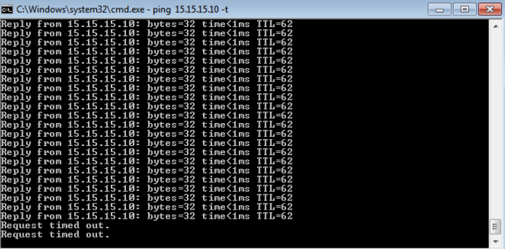
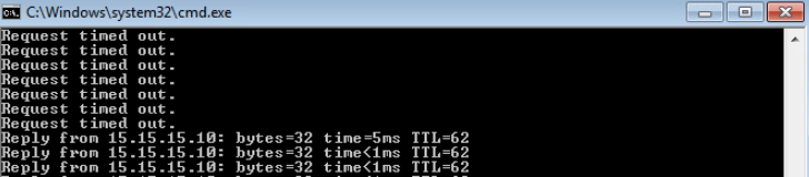
The test shows that the ICMP traffic is blocked as soon as the policy is applied.
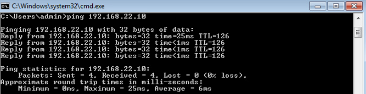
To demonstrate that our policy didn’t affect traffic within VPN 1, let’s ping the PC behind CSR02 at another site.
Adjust policy to allow ICMP traffic
This section will allow ICMP traffic to the Internet by modifying the policy.
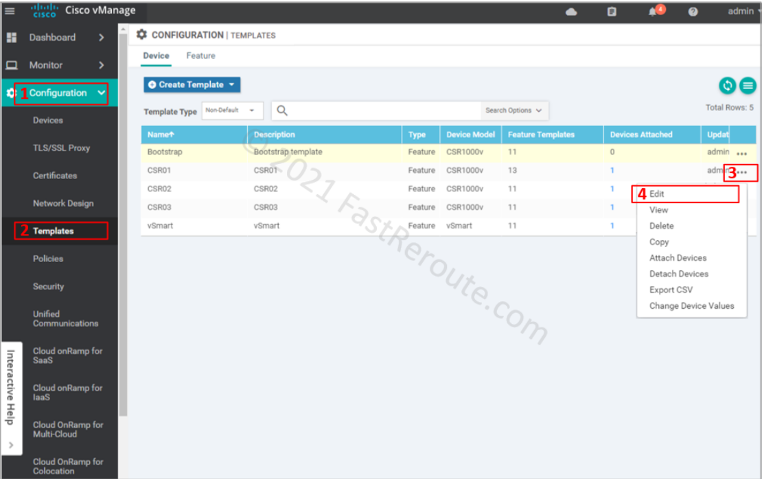
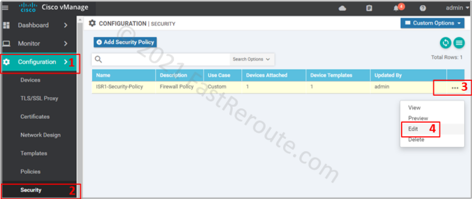
Return to the policy list via Configuration > Security. Choose the policy that we’ve created earlier and press Edit.
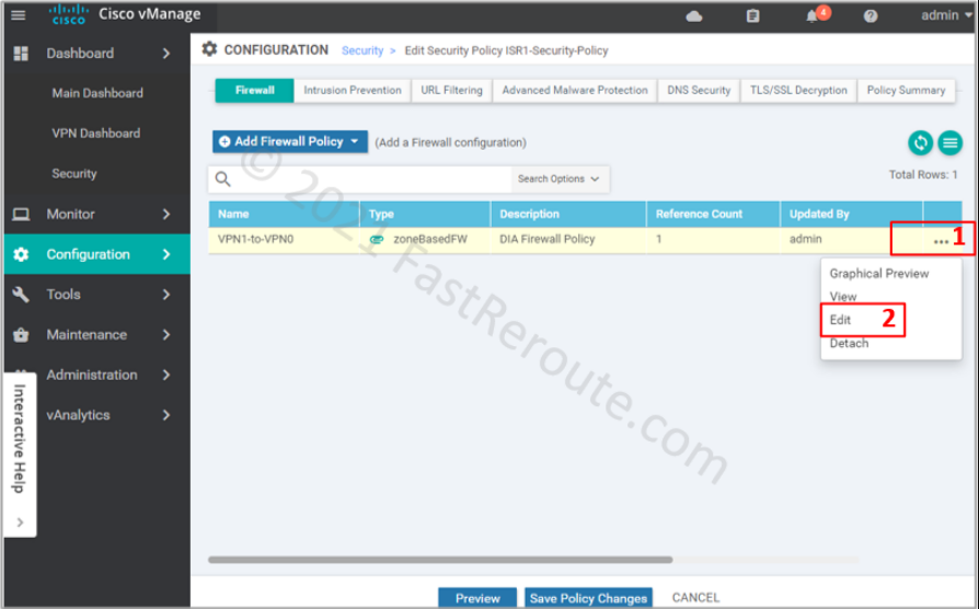
Click on the firewall section, choose the “VPN1-to-VPN0” firewall rule and press Edit.
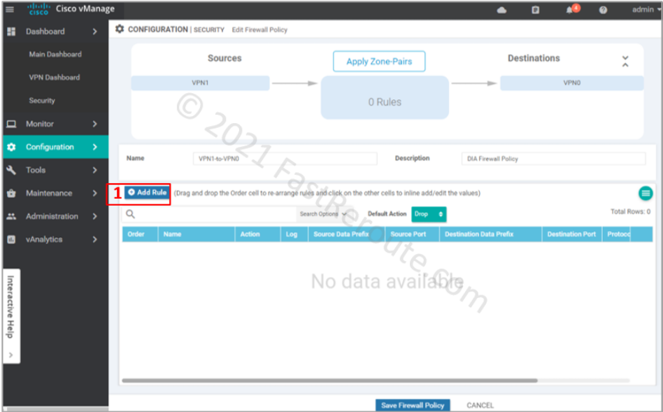
Add the new rule by clicking on the “Add Rule” button.
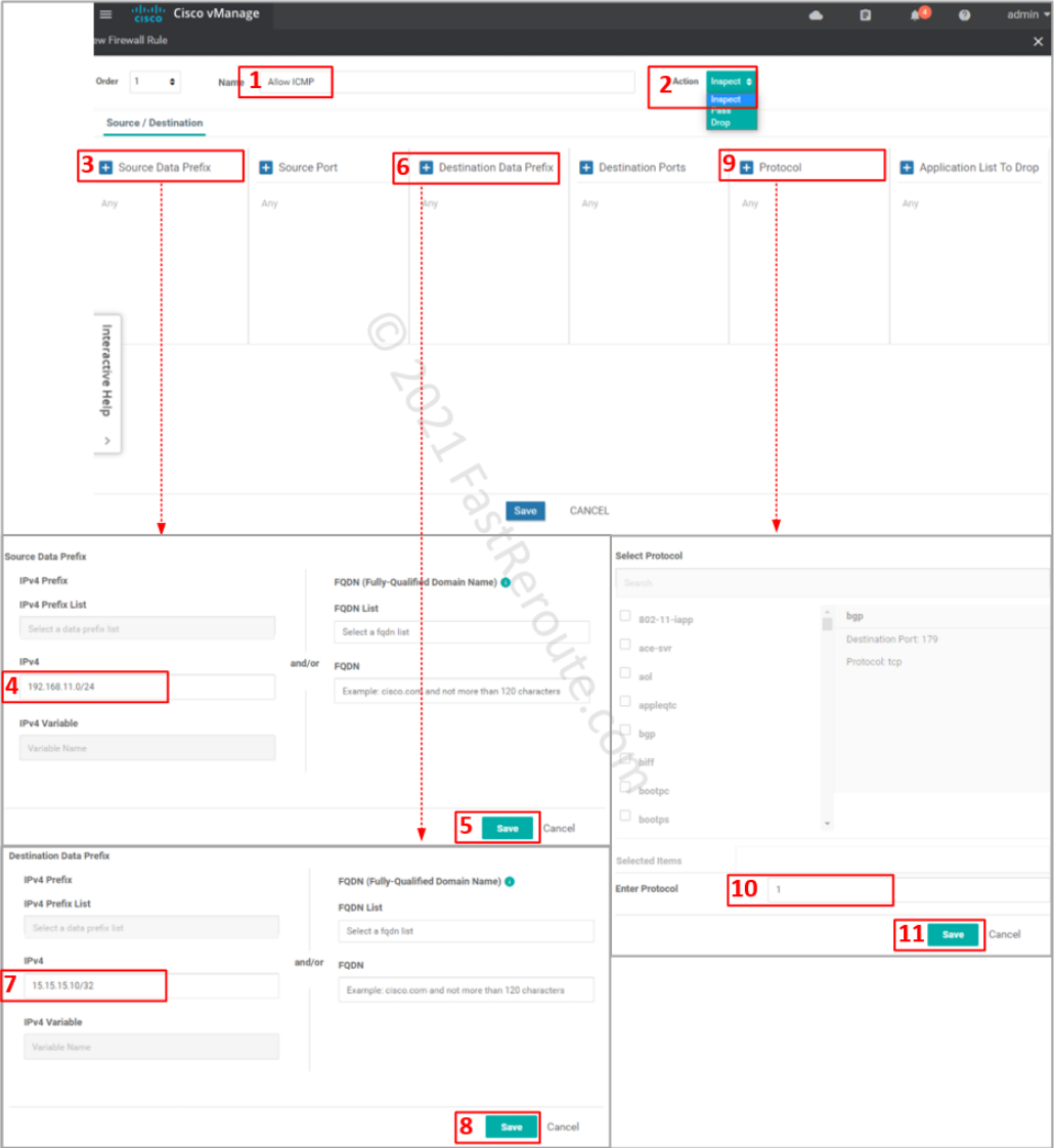
Specify ACL entry name and choose action to apply. Drop is self-descriptive. Inspect creates a stateful record of the session and automatically allows return traffic. Pass action – will not allow return traffic; for this action to work, you will be required to create another zone-pair for reverse direction and explicitly allow return traffic.
Define matching traffic and action. Protocol number 1 matches ICMP. Select one of the pre-defined protocols for TCP and UDP traffic. If unavailable or non-standard port numbers need to be specified, use ‘tcp’ or ‘udp’ as a protocol along with the “Destination Ports” condition.
Review the rule, save it, and its parent firewall policy.
vManage sends the following commands to the device.
The first three commands are object groups that identify the source, destination, and protocol.
Then access list is defined using the object groups. The class map that follows uses the ACL as a “match” condition.
Finally, policy-map now has a custom class-map statement placed above the default. The action for this traffic is ‘inspect,’ so return packets are automatically allowed.
object-group network VPN1-to-VPN0-seq-Allow_ICMP-network-dstn-og_
 host 15.15.15.10
object-group network VPN1-to-VPN0-seq-Allow_ICMP-network-src-og_
 192.168.11.0 255.255.255.0
object-group service VPN1-to-VPN0-seq-Allow_ICMP-service-og_
 icmp

ip access-list extended VPN1-to-VPN0-seq-Allow_ICMP-acl_
 permit object-group VPN1-to-VPN0-seq-Allow_ICMP-service-og_ object-group VPN1-to-VPN0-seq-Allow_ICMP-network-src-og_ object-group VPN1-to-VPN0-seq-Allow_ICMP-network-dstn-og_

class-map type inspect match-all VPN1-to-VPN0-seq-1-cm_
 match access-group name VPN1-to-VPN0-seq-Allow_ICMP-acl_

policy-map type inspect VPN1-to-VPN0
 class type inspect VPN1-to-VPN0-seq-1-cm_
  inspect
 class class-default
  drop
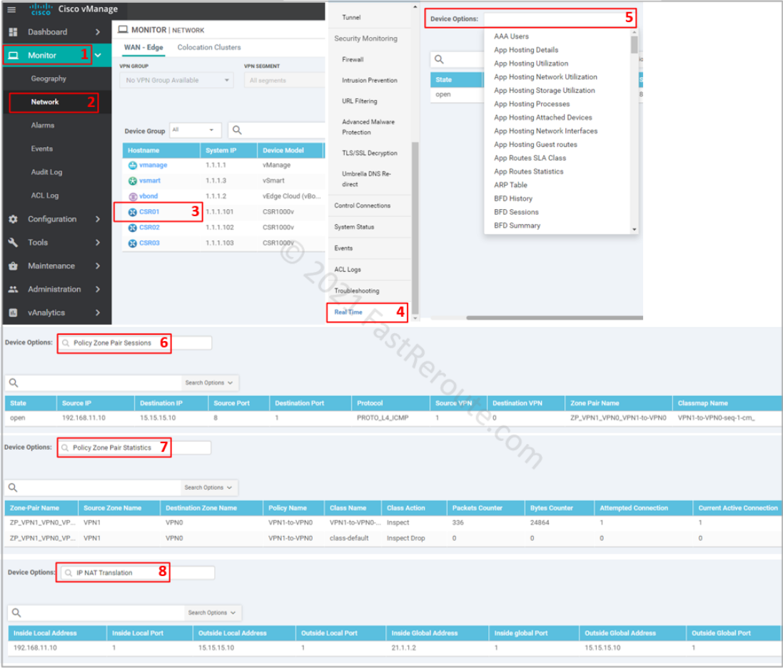
To monitor or troubleshoot firewall sessions, use the Real-Time menu in the device monitoring, as shown in the screenshot below. The following options provide relevant real-time information:
- Policy Zone Pair Sessions – displays list of sessions and which zone pair and class map is matched for each session
- Policy Zone Pair Statistics – shows statistics of packets and bytes matching per class-map
- IP NAT Translation – displays NAT translations, which can be useful in DIA troubleshooting scenarios
To view active sessions using CLI as they are passing, use show policy-firewall sessions command:
CSR01#show policy-firewall sessions platform ?
  all                     detailed information
  destination-port        Destination Port Number
  detail                  detail on or off
  icmp                    Protocol Type ICMP
  imprecise               imprecise information
  session                 session information
  source-port             Source Port
  source-vrf              Source Vrf ID
  standby                 standby information
  tcp                     Protocol Type TCP
  udp                     Protocol Type UDP
  v4-destination-address  IPv4 Desination Address
  v4-source-address       IPv4 Source Address
  v6-destination-address  IPv6 Desination Address
  v6-source-address       IPv6 Source Address
  |                       Output modifiers
  <cr>                    <cr>
It is possible to filter the output using one of the keywords above. We will display all sessions with ‘all’ keyword.
CSR01#show policy-firewall sessions platform all
--show platform hardware qfp active feature firewall datapath scb any any any any any all any --
[s=session  i=imprecise channel c=control channel  d=data channel A/D=appfw action allow/deny]
Session ID:0x00000001 192.168.11.10 8 15.15.15.10 1 proto 1 (1:1:1:1) (0x3:icmp)        [sc]
To display detailed information on the session, which includes ingress and egress interfaces, translated addresses, and other information use detail keyword.
CSR01#show policy-firewall sessions platform all detail
--show platform hardware qfp active feature firewall datapath scb any any any any any all any detail--
[s=session  i=imprecise channel c=control channel  d=data channel A/D=appfw action allow/deny]
Session ID:0x00000001 192.168.11.10 8 15.15.15.10 1 proto 1 (1:1:1:1) (0x3:icmp)        [sc]
 pscb : 0xebd9af00,  key1_flags: 0x00000000
        bucket : 57364, prev 0x0, next 0x0
    fw_flags: 0x00000000 0x2043ab61,
         Root Protocol-ICMP NAT-applied Initiator Alert Proto-State:Established No-halfopen-list Active-cnt egress-NATted Session-db Max-session
    icmp_error count 0 ureachable arrived: no
    scb state: active, nxt_timeout: 1000, refcnt: 1
    ha nak cnt: 0,  rg: 0
    hostdb: 0x00000000, L7: 0x, stats: 0xecb2e9c0, child: 0x00000000
    l4blk0: 0x00000a20 l4blk1: 0x00000000 l4blk2: 0x00000051 l4blk3: 0x00000000
    l4blk4: 0x00000a20 l4blk5: 0800000000 l4blk6: 0x00000051 l4blk7: 0x00000000
    l4blk8: cf5 l4blk9: 0x00000003
    root scb: 0x00000000 act_blk: 0xecb270f0
    ingress/egress intf: GigabitEthernet3 (1021), GigabitEthernet2 (65529)
    current time 16449437378761 create tstamp: 16367643249701 last access: 16448754360700
    nat_out_local_addr:port: 15.15.15.10:0
    nat_in_global_addr:port: 21.1.1.2:0
    syncookie fixup: 0x0,  halfopen linkage: 0x00000000 0x00000000
    cxsc_cft_fid: 0x00000000
    tw timer: 0x00000000 0x00000000 0x00000000 0x11018111
    Packets/session: 25     SGT: 0 DGT: 0, NAT handles 0xe9fdf840 0x00000000
    FlowDB in2out 0x00000000 out2in 0x00000000
    icmp_err_time 0, avc class stats 0x0, VPN id src 1, dst 0