Explain Role and Function of Network Components – Part 2 – Cisco Access Points and WLCs

This is the second part of the series of articles about the roles and functions of different network components (the first part is available here). In this part, we will discuss the operations of Cisco Wireless Access Points (APs) and Cisco WLAN Controllers (WLCs).  The purpose of this blog post is to explain what a Cisco-based wireless network consists of and how these elements interact with each other.

Wireless Standards

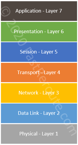
IEEE 802.11 set of standards defines Layer 1 and Layer 2 operations of wireless networks. The latest standard that Cisco Access Points support at the time of writing is 802.11ax (Wi-Fi 6).

IETF’s RFC 5415 standardizes communication protocol between a WLC and an Access Point – Control And Provisioning of Wireless Access Points (CAPWAP).

Access Points (APs)

Wireless clients connect to an Access Point to communicate with each other and with the devices on the wired network that the AP is connected to. Single Access Point forms a BSS (Basic Service Set), which is identified by its MAC address.

Access Point advertises one or many wireless networks identified by an SSID (Service Set ID). A WLAN can be mapped to a VLAN on the wired side of an access point.

ESSID is the same wireless network, as identified by an SSID but advertised by multiple Access Points that are connected to the same wired network.

Models

The current portfolio of Cisco Access Points is represented by:

  • Wi-Fi 6 (802.11ax) models, such as Catalyst 9115, 9117, 9120 and 9130
  • 802.11ac Wave 2 models, such as Aironet 1815, 2800, 3800 and 4800
  • Outdoor and Industrial, such as Aironet 1540, 1552, 1560 and 1570
  • Meraki MR45 and MR55
  • Small Business 100, 300 and 500 series

Cisco website provides a selector tool that performs a side-to-side comparison of different AP and controller models. It can be accessed via this URL.

Autonomous vs Lightweight APs

Access Point’s mode of operations can be either Autonomous or Controller-based. Let’s consider the difference between management, control and data planes for Access Points operating in different modes to understand their functions.

Management Plane

The management plane deals with the static configuration of Access Points. APs in autonomous mode can be managed directly via Web interface or CLI. In contrast, controller-based APs don’t allow direct configuration changes and, instead, are managed by the controller, which provides a centralized interface for an administrator. The controller is not always a dedicated physical or virtual appliance, it can also be cloud-based service (Meraki) or even another access point (Mobility Express and Embedded WLC).

Control Plane

The control plane is responsible for dynamic access point operations, such as radio parameters management and user authentication. Autonomous APs perform all these tasks on their own. Controller-based (or Lightweight) APs shift these tasks to the controller. For example, a controller can instruct access points to change a radio channel and decrease transmit power, as it can make more informed decisions based on data received from several adjacent access points in the network.

Data Plane

The Data plane is responsible for moving data between wireless clients and the wired networks. An autonomous AP switches data directly to the wired network based on its SSID-to-VLAN mapping. Lightweight APs have different mode operations which define how they switch data:

  • Local or Split MAC mode. In this mode, all user data traffic is tunneled to WLC
  • FlexConnect – central switching mode. Data plane is similar to local mode, however, some traffic can be switched locally. When the controller is not reachable, AP operates as an autonomous AP
  • FlexConnect – local switching mode. Data plane is similar to autonomous AP, which switches traffic locally to wired network based on configured SSID-to-VLAN mapping using 802.1q tagging
  • SD-Access mode. In this mode, AP connects to the SD-Access Edge switch and transmits data via SD-Access fabric using VXLAN encapsulation (check this link for more information on SD-Access).
Self-test question: What are the functions of an Access Point?
• Advertises one or more wireless networks identified by SSIDs and allows wireless clients to connect to these networks

• Allows wireless clients to communicate with each other and access wired network
Self-test question: What are the two modes of Access Points operations and their difference?
• Autonomous. Standalone Access Point that operates independently and is individually managed

• Lightweight or controller-based. Requires a controller to perform management and control plane tasks. Data plane operations may be performed locally or tunneled to WLC

Wireless LAN Controllers (WLCs)

Managing a number of autonomous APs is getting more difficult as device number grows, as the configuration must be consistent across many devices. WLCs solve this problem by providing centralized management of the wireless network.

Models

Current Cisco portfolio of controllers consists of:

  • WLC 3504 (AireOS)
  • WLC 5520 (AireOS)
  • WLC 8540 (AireOS)
  • Mobility Express on APs (AireOS)
  • Catalyst 9800 series (IOS-XE): 9800-L, 9800-40, 9840-80, 9800-CL (virtual)
  • Embedded WLC on APs and Switches (IOS-XE)

The recently released versions of WLCs can be compared using the same tool shown in the Access Points section.  

Software

Cisco Wireless LAN Controllers were traditionally running AireOS software. The Cisco controller-less solution with the WLC role performed by an 802.11ac Access Points is called Cisco Mobility Express.

Newer controllers are now IOS-XE software-based. New Catalyst 9100 Access Points can run the WLC role and this newer IOS-XE based solution is called Embedded Wireless Controller. Based on the fact that new controllers are IOS-XE based, AireOS most likely will be replaced by IOS-XE. A feature comparison of both platforms can be found here.

A controller can have multiple functions depending on types of the deployment. The next sections discuss available options.

Meraki cloud-based management

Meraki MR APs are first associated with their serial numbers with Meraki Cloud, which provides management access for the wireless LAN deployment. The AP-to-Controller communication is out-of-band and Meraki MR APs will continue to function when connectivity to Meraki Cloud is lost. During connectivity outages ability to perform configuration changes is not available.

No user data is being transferred through Meraki Cloud infrastructure. Security operations, such as authentication are performed by Meraki Access Point locally. For example, RADIUS authentication requests for WPA2 Enterprise are being sent directly from an access point.

Split-MAC

This type of deployment is suitable for large campuses, where sufficient infrastructure exists for the controller to be deployed locally. In this scenario, controllers are actively participating in data forwarding. Access Points establish CAPWAP tunnels to the controller. One tunnel is used for the control plane and another carries encapsulated data payload.

From a wired network perspective, all wireless users traffic is originating from WLC’s LAN interface. This simplifies the configuration of switching infrastructure, as access point facing ports no longer require 802.1q trunk configuration and maintenance of allowed VLANs on that interface. Such ports can be configured as access ports. CAPWAP traffic is unicast UDP traffic between the AP and the WLC.

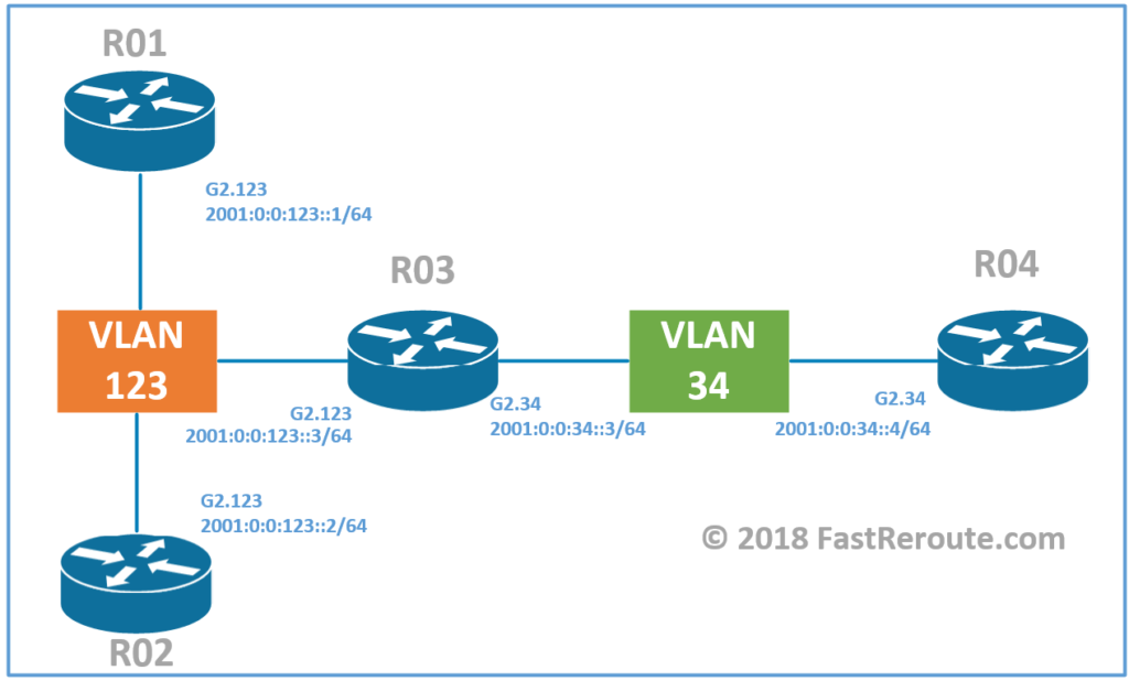
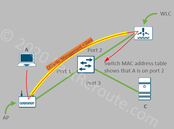
Figure 1 shows a simplified view of the traffic flow with the split MAC. If A sends a frame to C, AP will send it over the CAPWAP tunnel (in yellow) to WLC. AP and WLC can be in different VLANs, as CAPWAP is IP routed traffic. WLC will de-capsulate it and send it on its LAN interface connected to port 2 of the switch. The switch will learn the MAC address of A via port #2 (facing WLC).

Figure 1. Split MAC Traffic Flow

Split-MAC configuration usually offers faster roaming when the user moves from one access point to another. There are some associated drawbacks, such as the requirement to maintain a dedicated WLC, and bandwidth scaling limits imposed by the controller’s platform and increased dependency on the WLC, as Lightweight Access Points cannot operate without an active connection to it.

FlexConnect

The WLC and access points also support FlexConnect mode of operation. It allows Lightweight Access Point to locally switch some or all of the user traffic instead of sending it to the controller via the CAPWAP tunnel. This mode’s purpose is to decrease the amount of traffic that needs to be sent to a controller from the branch offices.

WLC appliances support 2 modes – Central Switching and Local Switching.

When WLAN is configured to use Central Switching, traffic from an AP is still tunneled to WLC, however, local-site traffic can be enabled for local switching by configuring Split Tunneling. When there is an active connection between WLC and AP, it is in Connected Mode. When the connection is lost, AP moves into a standalone mode and performs switching locally.

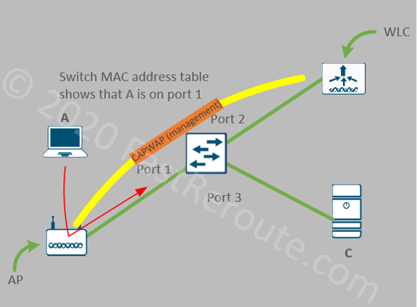
AP in FlexConnect Local Switching mode switches all traffic locally, even when AP can reach WLC. It is similar to the operation of autonomous APs which also switches traffic locally by mapping SSIDs to VLANs. Access Points are still controlled by WLC retaining the benefits of centralized management.

Figure 2. FlexConnect Local Switching Traffic Flow

Embedded WLCs (and Mobility Express) rely on FlexConnect Local Switching operation, as there is no benefit in sending encapsulated data over the tunnel to another Access Point that performs the role of WLC.

SD-Access Mode

SD-Access fabric-integrated WLC actively participates in the fabric operation via the control plane integration. For example, a WLC can update host tracking databases of the edge switch when a client registers, so this information is then distributed via a fabric LISP-based control plane.

WLC controls fabric-integrated access points perform the same functions as non-fabric WLCs, plus fabric specific operations. For example, a WLC provides an Access Point with VXLAN information (VNI) during client registration. By integrating with Cisco ISE, WLC can also provide AP with security tags (SGTs), so the policy can be enforced upstream.

In fabric mode, a WLC doesn’t participate in the data plane operation and all data is encapsulated locally by the fabric access point.

Self-test question: What are the functions of a WLC?
• Provide centralized management of the wireless network

• In some modes of operation transmit user traffic received from APs via CAPWAP tunnel
Self-test question: What are two types of the Cisco WLCs software?
• AireOS. This is the traditional Cisco WLC platforms software

• IOS-XE. New controllers are based on this version of the software
Self-test question: What is Split-MAC WLC mode of operation?
• An Access Points sends all user traffic to WLC where it breaks out centrally

The 3rd part of the series is now available.

Explain Role and Function of Network Components – Part 1

This blog post provides an overview of different network components and their role and functions. The article’s target audience is CCNA candidates and students looking for introductory information about computer network components. In this first post of the 3-article series, we will start by exploring the functions of endpoints and servers. Then the section about LAN switches will follow focusing on the difference between Layer 2 and Layer 3 switch operation.

Endpoints and Servers

The purpose of the infrastructure that the network devices create is to connect endpoints, such as computers, laptops, mobile and IP phones, and servers. A typical endpoint usually runs client applications, for example, a web browser and mail client that interact with the users. These network-enabled applications use services provided by network protocol stacks, drivers, and hardware components.

Out of all network components, endpoints have the most obvious role – they generate useful network payloads, such as digitized voice or Excel spreadsheets that are being transmitted over the network. And their function is to interact with a user, follow specific standards and protocols, so the transmitted data can be decoded on the receiving side of the connection.

Endpoints have an Operating System, which interacts with physical hardware using drivers. Operating System manages networking stack and provides APIs, so the application developers can work with the network without having to program low-level hardware components.

The most common type of wired connectivity is Ethernet, which is described by multiple IEEE 802.3 standards. Wireless communication is defined by IEEE 802.11 standards. Both types of connections use the same addressing, which is used to send frames between devices on the same network. Usually, this type of communication is referred to as Layers 1 and Layer 2 operations of the 7-layer OSI reference model. Layer 1 deals with physical specifications, such as electronic signals transferred over the wire. Layer 2 uses services provided by Layer 1 and is responsible for data framing and addressing.

Figure 1. OSI 7-Layer Model

Almost all OS stacks support and prefer one of two versions of IP protocol (IPv4 or IPv6). Each endpoint is assigned with an IP address that is used for addressing when a packet needs to be transmitted over multiple physical networks. This type of communication is referred to as Layer 3 connectivity.

There are two IP protocols operating on Layer 4 – Transport Control Protocol (TCP) and User Datagram Protocol (UDP). A connection or flow between two devices is identified by source and destination port (both TCP and UDP use concept of ports). Connection is usually initiated by a client. Servers wait for new connections to be established by listening on a specific port. TCP port 0 to 1023 are well-known ports allocated to the specific applications. Client-side uses dynamically allocated ports.

Layer 2 Switches

CCNA blueprint doesn’t include Ethernet hubs, as there are now fully replaced by the switches. However, it is still helpful to understand the way a hub operates to understand the benefits that Layer 2 switches provide.

Early Ethernet network technologies were either bus or star topology-based. Bus topology would have end devices sequentially connected to each other with a coaxial cable. A hub allowed building a star-like topology where all UTP (twisted pair) cabling would terminate in a single location with the hub being the center of the star. In both cases, the network was shared medium and each machine must first listen if there is an active transmission on the network before sending any traffic on its own.

If 2 devices send traffic at the same time a collision occurs and both devices pause for some random amount of time before trying again. Such mode of operation is called CSMA/CD (Carrier-Sense Multiple Access with Collision Detection).

Hubs create a collision domain by re-sending traffic to every port except the ingress one, which makes total available bandwidth smaller as the number of devices increases.

Layer 2 switch solves the issue of sending traffic to all ports by inspecting incoming traffic and learning addresses of devices behind each port, so it can then send unicast traffic through the correct port, as opposed to flooding. BUM traffic (Broadcast, Unknown Unicast and Multicast) is still sent out of all ports. Switches also can store some amount of traffic in its buffers if there is more traffic to be sent than the port’s available bandwidth.

Endpoints connected to a switched port don’t need to listen if other hosts on the network are sending traffic and can send data at any time. Such ports are operating in full-duplex and will not experience collisions as the devices connected to hub ports.

Ethernet Layer 2 switches are usually placed at the access level with the end-users, phones, and printers connected to them. Most of the Cisco Ethernet switches have 24 or 48 ports.

In the topology shown below, the switch uses only hardware MAC address information to forward frames. Both PCs and servers will also have Layer 3 address, such as IP or IPv6, however, for a Layer 2 switch operation, this information is not being processed for traffic forwarding.

Figure 2. Layer 2 Switch Operation

Layer 2 switches provide connectivity between hosts on Layer 2 with connected endpoints sharing the same broadcast domain and IP subnet. All 3 devices in the figure above are in the same VLAN and can communicate with each other. The switch will maintain a table of MAC address to port mappings.

Layer 2 switch can create broadcast domain boundaries by placing a group of ports into different VLANs, but it cannot provide communication between these domains. In the sample topology below A and B (ports 1 and 2) are in VLAN 10 and communicate with each other. C and D (ports 3 and 4) are in VLAN 20 and can also communicate with each other. There is no communication between VLAN 10 and VLAN 20 possible with only Layer 2 switch.

Figure 3. Layer 2 Switch Operation - VLANs
Figure 3. Layer 2 Switch Operation – VLANs

A layer 3 device is required to perform this function. In the campus network, it is the responsibility of a Layer 3 switches to provide connectivity between VLANs.

Self-test question: What are the functions of Layer 2 switch?
• Provide wired full-duplex connectivity to the end users and phones

• Divide collision domains. Each port is a separate collision domain

• Ability to create isolated broadcast domains with VLANs

Layer 3 Switches

Layer 3 switches traditionally were placed at the distribution level, however, in modern networks routed access becomes more common. Almost all current Cisco switching platforms can perform inter-VLAN routing and can act as Layer 3 switches on the network. Therefore, the distinction between Layer 2 and Layer 3 switches is in their configuration, not the specific model.

Layer 3 switching is essentially IP routing or packet forwarding based on Layer 3 addressing. Modern Layer 3 switches perform routing in hardware and can provide very high throughput comparable to Layer 2 switching. However, Layer 3 switches have a smaller feature sets when comparing to routers, which can usually be found at the WAN edge of the network.

To perform its operation Layer 3 switch must have either a logical interface in VLANs that it routes for or a physical interface with IP address assigned to it.

Switched Virtual Interface (SVI) is a logical interface named after VLAN it is connected to. It has an IP address allocated to it, to provide routing for this VLAN clients. As shown in the diagram below, Layer 3 switch has 2 SVIs – VLAN10 and VLAN20. Notice that now devices are shown with IPv4 addresses allocated to them instead of hardware MAC addresses, as this is the information relevant for Layer 3 switch operation.

Layer 2 operations are still performed in exactly the same way as described in the Layer 2 switch section. For example, if the workstation A sends a packet to the server B, no routing is required and Layer 2 forwarding is used to deliver the frame.

If host A will try to communicate to host D inter-VLAN routing will be performed by the switch, which will involve two-step process – Layer 2 communication between host A and switch VLAN 10 SVI; and another one between switch’s VLAN 20 SVI and the server D.

Figure 4. Layer 3 Switch Operation – SVIs

Physical IP interfaces are usually used on transit segments. Consider the topology shown in the next diagram. Switch connects to two routers. A point-to-point subnet of /30, which can accommodate only 2 hosts, has been to allocate to each of the connections. We now have two configuration options. The top router is connected via Layer 2 port which is a member of VLAN 254. We then create an SVI on the L3 switch for VLAN 254. As we assigned only a single Layer 2 port to this VLAN, the connection is point-to-point. This is similar to the previous example.

The second option is to configure the physical port, in our case, it is GigabitEthernet1/0/10 as Layer 3 port. We don’t have to consume a VLAN ID and configuration is contained within a single interface.

Figure 5. Layer 3 Switch Operation – L3 Interfaces
Self-test question: What are the functions of Layer 3 switch?
• Can perform all functions of Layer 2 switch

• Performs high-speed routing between VLANs

• Traditionally deployed at distribution layer of the campus network

• Can be deployed at the access layer when routed access design is used

In the second part of these series of articles, we will discuss the operation of another type of LAN device which provides connectivity to the wireless clients – Access Points. Wireless LAN Controller functions will also be presented.

The third part of this series will be dedicated to devices that are usually found at the edge of the network, such as routers, firewalls, and IPSs.

DNA Center is introduced in its own article.

Reference materials

Cisco SD-Access

Collapsed core and three-tier architecture

Cisco Certification Changes

Cisco Certification Levels

This blog post provides information about the Cisco certification program after the February 2020 update, which has not only affected exam blueprints but also consolidated and renamed many certification tracks. In summary, the changes made are:

  • Previous multiple CCNA tracks are now discontinued. Only a single track is called CCNA, i.e. no more CCNA specializations. Associate-level DevNet and CyberOps certifications are still available, however, CCNA is removed from their name.
  • Design-focused associate and professional tracks (CCDA and CCDP) have been removed.
  • Different CCNP tracks are still available. CCNP status now requires passing only 2 exams: a core and one of the concentration exams which can be selected.
  • Introduction of multiple specialist certifications. Every concentration exam from the CCNP track also earns a specialist certification.
  • Various CCIE tracks are still available with some adjustments. The lab format is changed. The written exams are now replaced with the core exams, which are shared with the corresponding CCNP track.

Entry-level Certification

CCT Certification
CCT Certification

CCT Data Center and CCT Routing and Switching

Cisco Certified Technician (CCT) Data Center and Routing and Switching tracks focus on onsite support and maintenance of data center equipment (such as UCS servers and Nexus switches) or enterprise devices (routers and switches). Technicians must be able to identify device models and components, as well as cabling and accessories. The exam also tests some knowledge of basic configuration. CCT Data Center requires the passing of the DCTECH exam with code of 010-151 and the CCT Routing & Switching exam code is 100-490 RSTECH.

Associate-level Certification

There are 3 associate-level certifications available: CCNA, CyberOps Associate and DevNet Associate.

CCNA Certification
CCNA Certification

CCNA

New CCNA is a broad foundation certification that now includes the topics that were previously part of CCNA Routing and Switching, Wireless, and Security. It also encompasses topics from now-retired design track – CCDA.

CCNA tests a candidate’s fundamental knowledge and covers a broad set of topics. Engineers starting their career in networking do not to have to make a specialization decision early. To achieve CCNA certification only 1 exam is required – 200-301. Exam topics include network fundamentals, such as LAN switching, wireless, and introductory IP routing and services. The exam also contains security and automation-related questions.

CyberOps Associate

This certification track is for the Security Operation Center (SOC) Analysts. At the time of writing, 2 exams are required to achieve this certification. Cisco has announced the plan to replace these exams with a single consolidated exam in May 2020. A detailed list of the exam topics is available via the URLs below:

  • 210-250 SECFND (available till May 2020)
  • 210-255 SECOPS (available till May 2020)

DevNet Associate

DevNet certification tracks are for the engineers looking into application development for Cisco products and platforms. A single exam is required – 200-901 (DEVASC: DevNet Associate). A list of the exam topics is available via this link.

Certified individuals will have knowledge in different data formats, Cisco platforms API capabilities and popular automation tools.

Professional-level Certification

There are 6 professional-level tracks currently available, with 5 of them are called CCNP:  

  • CCNP Enterprise
  • CCNP Service Provider
  • CCNP Data Center
  • CCNP Security
  • CCNP Collaboration
  • DevNet Professional

There are no formal pre-requisites in obtaining professional-level certifications, so one can skip CCNA certification. Re-certification is required every three years. Each track has one required core exam and one elective concentration exam.

Concentration exams also award an associated specialist certification, so every CCNP will have at least a single specialist-level certification that corresponds to the selected concentration exam.

CCNP Certification
CCNP Certification

CCNP Enterprise

CCNP Enterprise consolidates topics from several previously available certifications – CCNP Routing and Switching, CCNP Wireless and CCDP. Some of the shared topics are now tested as part of the core exam and then there are the specific technology-focused concentration exams.

Core exam for CCNP Enterprise is:

  • 350-401 ENCOR:  Implementing and Operating Cisco Enterprise Network Core Technologies.

Candidates can select a single exam from the list below to earn CCNP Enterprise certification.

  • 300-410 ENARSI: Implementing Cisco Enterprise Advanced Routing and Services
  • 300-415 ENSDWI: Implementing Cisco SD-WAN Solutions
  • 300-420 ENSLD: Designing Cisco Enterprise Networks
  • 300-425 ENWLSD: Designing Cisco Enterprise Wireless Networks
  • 300-430 ENWLSI: Implementing Cisco Enterprise Wireless Networks
  • 300-435 ENAUTO: Implementing Automation for Cisco Enterprise Solutions

As each of the exams above also earns a Specialist certification it will be possible to see which areas individual has expertise in.

CCNP Service Provider

Certification track information is available via this link. Core exam (mandatory):

  • 350-501 SPCOR: Implementing and Operating Cisco Service Provider Network Core Technologies

Concentration exams (select one):

  • 300-510 SPRI: Implementing Cisco Service Provider Advanced Routing Solutions
  • 300-515 SPVI: Implementing Cisco Service Provider VPN Services
  • 300-535 SPAUTO: Implementing Automation for Cisco Service Provider Solutions

CCNP Data Center

This track is for Data Center engineers and designers. Core exam (mandatory):

  • 350-601 DCCOR: Implementing and Operating Cisco Data Center Core Technologies

Concentration exams (select one):

  • 300-610 DCID: Designing Cisco Data Center Infrastructure
  • 300-615 DCIT: Troubleshooting Cisco Data Center Infrastructure
  • 300-620 DCACI: Implementing Cisco Application Centric Infrastructure   
  • 300-625 DCSAN: Implementing Cisco Storage Area Networking
  • 300-635 DCAUTO: Automating and Programming Cisco Data Center Solutions

CCNP Security

This certification. It is for network engineers specializing in Cisco security portfolio. Core exam (mandatory):

  • 350-701 SCOR: Implementing and Operating Cisco Security Core Technologies

Concentration exams (select one):

  • 300-710 SNCF: Securing Networks with Cisco Firepower Next Generation Firewall and IPS
  • 300-715 SISE: Implementing and Configuring Cisco Identity Services Engine
  • 300-720 SESA: Securing Email with Cisco Email Security Appliance
  • 300-725 SWSA: Securing the Web with Cisco Web Security Appliance
  • 300-730 SVPN: Implementing Secure Solutions with Virtual Private Networks
  • 300-735 SAUTO: Implementing Automation for Cisco Security Solutions

CCNP Collaboration

Professional level certification for voice/collaboration engineers. Certification track information is available via this link.

Core exam (mandatory):

  • 350-801 CLCOR: Implementing and Operating Cisco Collaboration Core Technologies

Concentration exams (select one):

  • 300-810 CLICA: Implementing Cisco Collaboration Applications
  • 300-815 CLACCM: Implementing Cisco Advanced Call Control and Mobility Services
  • 300-820 CLCEI: Implementing Cisco Collaboration Cloud and Edge Solutions
  • 300-835 CLAUTO: Implementing Automation for Cisco Collaboration Solutions

DevNet Professional

Many of DevNet Professional concentration exams are shared with other CCNP tracks. Core exam (mandatory):

  • 350-901 DEVCOR: Developing Applications Using Cisco Core Platforms and APIs

Concentration exams (select one):

  • 300-435 ENAUTO: Implementing Automation for Cisco Enterprise Solutions
  • 300-535 SPAUTO: Implementing Automation for Cisco Service Provider Solutions
  • 300-635 DCAUTO: Implementing Automation for Cisco Data Center Solutions
  • 300-735 SAUTO: Implementing Automation for Cisco Security Solutions
  • 300-835 CLAUTO: Implementing Automation for Cisco Collaboration Solutions
  • 300-910 DEVOPS: Implementing DevOps Solutions and Practices using Cisco Platforms
  • 300-915 DEVIOT: Developing Solutions using Cisco IoT and Edge Platforms
  • 300-920 DEVWBX: Developing Applications for Cisco Webex and Webex Devices

Expert-level Certification

Cisco’s CCIE program is one of the most respected certifications in the industry. There are 7 expert-level certifications, 6 x CCIE, and CCDE. All CCIE exams share core exam with the CCNP tracks as pre-requisite and 8-hours lab hands-on practical exam.

CCIE Certification
CCIE Certification

New lab exams for CCIE tracks availability date is April 27, 2020. The new format of the exam includes 2 modules: 3-hours design and 5-hours for tasks testing deployment and operation of the lab network.

CCIE Enterprise Infrastructure

Written exam (the same exam required for CCNP Enterprise):

  • 350-401 ENCOR: Implementing and Operating Cisco Enterprise Network Core Technologies.

Practical exam:

  • CCIE Enterprise Infrastructure v1.0 replaces Routing and Switching lab exam and covers topics as traditional routing and switching, services and software-defined infrastructure. Blueprint also includes automation and programmability topics.

CCIE Enterprise Wireless

Written exam (the same exam required for CCNP Enterprise):

  • 350-401 ENCOR: Implementing and Operating Cisco Enterprise Network Core Technologies.

Practical exam:

CCIE Collaboration

Written exam (the same exam required for CCNP Collaboration):

  • 350-801 CLCOR: Implementing and Operating Cisco Collaboration Core Technologies

Practical exam:

CCIE Data Center

Written exam (the same exam required for CCNP Data Center):

  • 350-601 DCCOR: Implementing and Operating Cisco Data Center Core Technologies

Practical exam:

  • CCIE Data Center v3.0 includes ACI and VXLAN EVPN, Compute and Storage. There is also 15% of data center automation topics.

CCIE Security

Written exam (the same exam required for CCNP Security):

  • 350-701 SCOR: Implementing and Operating Cisco Security Core Technologies

Practical exam:

  • CCIE Security v6.0 practical exam includes Cisco firewalls, ISE, and advanced threat protection-related tasks.

CCIE Service Provider

Written exam (the same exam required for CCNP Service Provider):

  • 350-501 SPCOR: Implementing and Operating Cisco Service Provider Network Core Technologies

Practical exam:

  • CCIE Service Provider v5.0 practical exam covers service provider technologies, including provider-specific routing and security, MPLS and automation.

CCDE

Written exam (CCDE exam has its own written exam, as there is no CCDP anymore):

Practical exam:

  • CCDE practical exam has a different format from CCIE exams. It is also a 8-hours exam focusing on design case studies

Architect-level Certification

CCAr is the highest level of Cisco certification. It has a pre-requisite of passing the CCDE exam and submitting an application outlining the past project experience. After approval candidate must complete the CCAr Board Exam which is based on presenting a network architecture to a panel of Board members.

Specialist Certification

Specialist certifications usually require only a single exam to be passed. Apart from specializations achieved by passing concentration exams from CCNP tracks, there are 14 specialist certifications which cover very focused areas of technology or business:

  • Cisco TelePresence Solutions Specialist 
  • Cisco Unified Contact Center Enterprise Specialist            
  • Cisco Video Network Specialist
  • Cisco and NetApp FlexPod Design Specialist        
  • Cisco and NetApp FlexPod Implementation and Administration Specialist              
  • Cisco Industrial Networking Specialist                     
  • Cisco IOS XR Specialist                    
  • Cisco Service Provider Mobility CDMA to LTE Specialist   
  • Cisco Service Provider Mobility UMTS to LTE Specialist    
  • Cisco Business Architecture Analyst                       
  • Cisco Business Architecture Specialist                                    
  • Cisco Business Architecture Practitioner
  • Cisco Customer Success Manager
  • Cisco Renewals Manager                            

This URL contains up-to-date information on these tracks.

Related technology posts:

Cisco Data Center: ACI Concepts

Cisco Data Center: VPC Basics

Network Design Architectures

Cisco Enterprise: SD-Access Components

Cisco SD-WAN: Overview

Cisco SD-WAN: Routers and Platforms

IPv6: Addressing Scheme

IPv6: Configure, Verify and Troubleshoot

Configure SNMP on Cisco Devices

Configure SNMP on Cisco Devices

SNMP Overview

SNMP (Simple Network Management Protocol) defines communication and message format between network management stations and agents.

Every managed network element, such as a router, switch, or host is running a management agent. Its function is to retrieve and modify operational variables’ values as requested by network management stations.

This article contains information on how to enable SNMP agents on different Cisco devices, including IOS, IOS-XE, and NX-OS-based.

SNMPv1/SNMPv2c Configuration

SNMPv1 and SNMPv2c use the same security mechanisms based on communities transmitted in clear-text format. It is still used in some networks, however, SNMPv3 should be used in new deployments.

I will start with SNMPv1 and SNMPv2 configuration first. SNMPv3 configuration will be shown in the later sections.

I’m using 3 different types of devices in this demonstration: Classic IOS, IOS-XE, and NX-OS. The community string is the only required configuration and it is the same for SNMPv1/v2c on our platforms with slightly different keyword options on NX-OS.

Classic IOS (Cisco 1940)

You can specify if the community string is for read-only and read-write access, as well as access-list to control which management stations are allowed to query the device. All options except for community string are optional, with read-only access being the default if none is specified. You can enter more than one community string, as the command doesn’t overwrite previous community value.

C1940(config)#snmp-server community FastRerouteRO ?
<1-99> Std IP accesslist allowing access with this community
string
<1300-1999> Expanded IP accesslist allowing access with this
community string
WORD Access-list name
ipv6 Specify IPv6 Named Access-List
ro Read-only access with this community string
rw Read-write access with this community string
view Restrict this community to a named MIB view

C1940(config)#snmp-server community FastRerouteRO ro
C1940(config)#snmp-server community FastRerouteRW rw

IOS-XE (CSR1000V)

IOS-XE has the same options and keywords as classic IOS:

CSR1000V(config)#snmp-server community FastRerouteRO ?
<1-99> Std IP accesslist allowing access with this community
string
<1300-1999> Expanded IP accesslist allowing access with this
community string
WORD Access-list name
ipv6 Specify IPv6 Named Access-List
ro Read-only access with this community string
rw Read-write access with this community string
view Restrict this community to a named MIB view

CSR1000V(config)#snmp-server community FastRerouteRO ro
CSR1000V(config)#snmp-server community FastRerouteRW rw

NX-OS (Nexus 9000V)

N9K-1(config)# snmp-server community FastRerouteRO ?

group Group to which the community belongs
ro Read-only access with this community string
rw Read-write access with this community string
use-ipv4acl Specify IPv4 ACL, the ACL name specified
after must be IPv4 ACL.
use-ipv6acl Specify IPv6 ACL, the ACL name specified
after must be IPv6 ACL.

N9K-1(config)#snmp-server community FastRerouteRO ro
N9K-1(config)#snmp-server community FastRerouteRW rw

NMS Configuration

To test the configuration I will be using a great free application called SnmpB (link). For each device, you will require an Agent Profile. Press the Tools button as shown in Figure 1.

Figure 1. SnmpB User Interface
Figure 2. SnmpB Agent Profile Configuration

I’ve created a profile for each of the 3 devices. The settings are shown in Figure 3.

My Cisco 1940 router’s IP address is 172.16.17.1 with the SNMP community of FastRerouteRO as shown in Figure 4.

Figure 3. SnmpB Agent Profile General Settings
Figure 4. Agent Profile SNMPv1/v2c Settings

Once profiles are configured, let’s test simple get request for the device uptime. We need to request (using SNMP GET) value of an object that represents device uptime. Any object in SNMP has a unique identifier (OID) and its format and description will be defined in a MIB.

What is MIB and OID?

As per RFC1155 (link) – “Managed objects are accessed via a virtual information store, termed the Management Information Base or MIB… Each type of object (termed an object type) has a name, a syntax, and an encoding. The name is represented uniquely as an OBJECT IDENTIFIER. An OBJECT IDENTIFIER is an administratively assigned name.”

MIB describes a set of objects, including their identifiers, expected reply format, and if values are read-only or can be changed.

For example, MIB-II has the following definition for interface description:

Figure 5. SNMP Interface Description Object

A network device usually supports a standard-based MIB, such as MIB-II (link), as well as vendor-proprietary MIBs. Most NMS have pre-loaded modules for standard MIBs. Import is required to support vendor-specific extensions.

Object Identifier (OID) is written in dotted notation starting with the top-level node. For example, the Internet subtree of Object Identifiers is 1.3.6.1. The object hierarchy has an unlabelled root. Under root, there are 3 allocated child nodes: ccitt (0), iso (1), and joint-iso-ccitt (2).

ISO has a subtree for other organizations org (3), with the child node of (6) assigned to the US Department of Defense (DOD). DoD in turn allocated a node (1) to Internet Activities Board (IAB).

SNMPv2 Testing

To test – expand the MIB tree and navigate to sysUpTime object (1.3.6.1.2.1.1.3). Note that the Node Info window displays detailed information about the selected object. Right-click on sysUpTime and then select Get.

Figure 6. Get Request for sysUpTime

The Figure 7 shows uptime of the Cisco 1940 router.

Figure 7. Reply for sysUpTime (Cisco 1940)

Figure 8 and Figure 9 shows uptime of the Nexus 9000V and CSR. To poll different devices select the corresponding entry in the drop-down box called Remote SNMP Agent.

Figure 8. Reply for sysUpTime (Nexus 9000V)
Figure 9. Reply for sysUpTime (CSR1000)

SNMPv3 Configuration

SNMPv3 defines the User-based Security Model (USM) with the ability to authenticate and encrypt communication between agents and monitoring stations. There are 3 security levels listed below with the weakest first:
• noAuthNoPriv (no authentication or encryption)
• authNoPriv (authentication only)
• authPriv (authentication and encryption)

Minimal configuration of SNMPv3 requires 2 components: Group and User.

Note: There are some interoperability issues between Cisco IOS and IOS-XE devices and SnmpB when AES192 and AES256 used, so AES128 is configured instead in all examples. SNMP debug (debug snmp detail and debug snmp packets) produce the following error with AES192 and AES256:

*Dec 26 02:47:55.691: SNMP: Packet received via UDP from 172.16.17.75 on GigabitEthernet1no such type in ParseType (152) (0x98)
ParseSequence, Unexpected type: FFFFFFFFFFFFFFFF
SrParseV3SnmpMessage: ParseSequence:
SrParseV3SnmpMessage: Failed.
SrDoSnmp: ASN Parse Error
*Dec 26 02:47:58.693: SNMP: Packet received via UDP from 172.16.17.75 on GigabitEthernet1no such type in ParseType (152) (0x98)
ParseSequence, Unexpected type: FFFFFFFFFFFFFFFF
SrParseV3SnmpMessage: ParseSequence:
SrParseV3SnmpMessage: Failed.
SrDoSnmp: ASN Parse Error

Classic IOS (Cisco 1940)

C1940(config)#snmp-server group SNMP-Group v3 ?                                                      
auth group using the authNoPriv Security Level
noauth group using the noAuthNoPriv Security Level
priv group using SNMPv3 authPriv security level

C1940(config)#snmp-server group SNMP-Group v3 priv
C1940(config)#snmp-server user SNMP-Admin SNMP-Group v3
auth sha FastReroute priv aes 128 FastReroute

Note: SNMP users are not stored as part of running or startup configuration, so the second line will not be visible via “show running-config“.

SnmpB requires the configuration of SNMPv3 User. To access the configuration setting click on Options > Manage SNMPv3 USM Profile. Once the USM profile window opens, right-click on a blank space in the list of profiles and select “New USM profile”. I’ve configured username, security parameters to match the ones we configured on the router earlier. See Figures 9 and 10 for details.

Figure 9. SnmpB: SNMP User Configuration
Figure 10. SnmpB: SNMP User Configuration – 2

Go back to our device profiles, as shown in the Figure 1. Select SNMPv3 as supported version and choose corresponding Security Name and Levels as shown in Figure 11 and 12.

Figure 11. SnmpB: Enable SNMPv3
Figure 12. SnmpB: Enable SNMPv3 – 2

Let’s try to poll the Cisco 1940 to confirm that we still can access uptime information as shown in Figure 13.

Figure 13. SnmpB: Poll Uptime with SNMPv3 Enabled (Cisco 1940)

IOS-XE (CSR1000V)

IOS-XE is configured identically as Classic IOS.

CSR1000V(config)#snmp-server group SNMP-Group v3 priv
CSR1000V(config)#snmp-server user SNMP-Admin SNMP-Group v3
auth sha FastReroute priv aes 128 FastReroute
Figure 14. SnmpB: Poll Uptime with SNMPv3 Enabled (CSR1000)

NX-OS (Nexus 9000V)

Nexus 9000V minimal configuration is based on a single string, as SNMP groups in NX-OS are replaced by roles for Role-Based Access Control, and by default new users will be assigned network-operator permissions. As a side effect, by default SNMP users will be able to log-in via CLI to the switch with access to all show commands.

Note that there is no group option under SNMP. Use the “role” set of commands, which then can be used as groups in SNMP.

N9K-1(config)# snmp-server ?
aaa-user Set duration for which aaa-cached snmp user
exists
community Set community string and access privs
contact Modify sysContact
context SNMP context to be mapped
counter Configure port counter configuration
drop Silently drop unknown v3 user packets
enable Enable SNMP Traps
engineID Configure a local SNMPv3 engineID
globalEnforcePriv Globally enforce privacy for all the users
host Specify hosts to receive SNMP notifications
location Modify sysLocation
mib Mib access parameters
packetsize Largest SNMP packet size
protocol Snmp protocol operations
source-interface Source interface to be used for sending out SNMP
notifications
system-shutdown Configure snmp-server for reload(2)
tcp-session Enable one time authentication for snmp over tcp
session.
user Define a user who can access the SNMP engine

You can assign users to a group for SNMP-Admin by typing it in straight after the username.

N9K-1(config)# snmp-server user SNMP-Admin ?

WORD Group name (ignored for notif target user) (Max Size
28)
auth Authentication parameters for the user
enforcePriv Enforce privacy for the user
use-ipv4acl Specify IPv4 ACL, the ACL name specified after must be
IPv4 ACL.
use-ipv6acl Specify IPv6 ACL, the ACL name specified after must be
IPv6 ACL.

N9K-1(config)# snmp-server user SNMP-Admin auth
sha FastReroute priv aes-128 FastReroute

NX-OS also creates a normal user in addition to the SNMP user. Both users are stored in the running configuration.

N9K-1(config)# show run | incl SNMP 

username SNMP-Admin password 5 #password# role network-operator

snmp-server user SNMP-Admin network-operator auth sha
#password# priv aes-128 #password# localizedkey

Let’s test that we can poll N9K using SNMPv3.

Figure 15. SnmpB: Poll Uptime with SNMPv3 Enabled (Nexus 9000V)

SNMP show commands

Classic IOS (Cisco 1940) and IOS-XE (CSR1000V)

Devices keep track of which objects were polled and associated timestamps, as shown in the listings below.

CSR1000V#show snmp stats oid 

time-stamp #of times requested OID
03:27:46 UTC Dec 21 2018 6 sysUpTime
09:54:49 UTC Dec 18 2018 3 system.6
09:54:46 UTC Dec 18 2018 3 system.4
09:53:49 UTC Dec 18 2018 2 system.5
09:53:49 UTC Dec 18 2018 2 system.1
11:27:41 UTC Dec 17 2018 1 sysOREntry.3

To get the list of SNMP groups use the “show snmp group” command. Note that SNMPv1 and SNMPv2c have groups and as there is no concept of users, they are named as the community name. Also not covered in this article, SNMP views allow restricting access only to specific OIDs or subtrees.

CSR1000V#show snmp group
groupname: ILMI security model:v1
contextname: storage-type: permanent
readview : *ilmi writeview: *ilmi
notifyview:
row status: active

groupname: ILMI security model:v2c
contextname: storage-type: permanent
readview : *ilmi writeview: *ilmi
notifyview:
row status: active

groupname: SNMP-Group security model:v3 priv
contextname: storage-type: nonvolatile
readview : v1default writeview:
notifyview:
row status: active

groupname: FastRerouteRO security model:v1
contextname: storage-type: permanent
readview : v1default writeview:
notifyview:
row status: active

groupname: FastRerouteRO security model:v2c
contextname: storage-type: permanent
readview : v1default writeview:
notifyview:
row status: active

groupname: FastRerouteRW security model:v1
contextname: storage-type: permanent
readview : v1default writeview: v1default
notifyview:
row status: active

groupname: FastRerouteRW security model:v2c
contextname: storage-type: permanent
readview : v1default writeview: v1default
notifyview:
row status: active

To get the list of SNMP users use the “show snmp user” command. As users are not displayed in the configuration, this command is the only way to check the SNMP users.

CSR1000V#show snmp user
User name: SNMP-Admin
Engine ID: 800000090300000C29B86282
storage-type: nonvolatile active
Authentication Protocol: SHA
Privacy Protocol: AES128
Group-name: SNMP-Group

NX-OS (Nexus 9000V)

N9K-1# show snmp oid-statistics 

SNMP OID Stats -
Object ID Min Max Avg
Max Access TS Last-polled NMS Poll Count
(ms) (ms) (ms)

iso.3.6.1.2.1.1.3 <1 <1 <1
02:33:25:515 Dec 21 2018 172.16.17.75 1

NX-OS in addition to OID statistics also provides show command to display statistics related to a management station.

N9K-1# show snmp nms-statistics 

- SNMP NMS OID Stats -
 
NMS IP Address                              GET    GET    GET    SET           
First Poll                 Last Poll
                                                  NEXT   BULK
--------------------------------------------------------------------------------
----------------------------------------
172.16.17.75                                  1      0      0      0 
02:33:25:515 Dec 21 2018  02:33:25:515 Dec 21 2018

To get the list of SNMP groups use the “show snmp group” command. Its output is the same as the “show role” command would produce.

N9K-1(config)# show snmp group 

Role: aaa-db-admin
Description: Predefined AAA DB admin, has no cli permissions. Allows RESTful A
PI

Rule Perm Type Scope Entity

1 permit read-write

#some output omitted

Role: network-admin
Description: Predefined network admin role has access to all commands
on the switch

Rule Perm Type Scope Entity

1 permit read-write
Role: network-operator
Description: Predefined network operator role has access to all read
commands on the switch

Rule Perm Type Scope Entity

1 permit read

#some output omitted

To get the list of SNMP users use the “show snmp user” command. Admin users are automatically enabled as SNMP users, as NX-OS implements a single user and role storage.

N9K-1(config)# show snmp user
SNMP USERS

User Auth Priv(enforce) Groups acl_filter
_ __ _ ___
admin md5 des(no) network-admin
SNMP-Admin sha aes-128(no) network-operator

NOTIFICATION TARGET USERS (configured for sending V3 Inform)

User Auth Priv
_ ___

SNMP debug commands

Classic IOS (Cisco 1940) and IOS-XE (CSR1000V)

Two commands displaying if there is communication with NMS are “debug snmp detail” and “debug snmp packets“. Below is the output generated when a simple SNMP Get request is performed.

CSR1000V#debug snmp detail
SNMP Detail Debugs debugging is on
CSR1000V#debug snmp packets
SNMP packet debugging is on
CSR1000V#terminal monitor
*Dec 26 23:41:59.539: SNMP: Packet received via UDP from 172.16.17.75 on GigabitEthernet1SrParseV3SnmpMessage: Failed..


*Dec 26 23:41:59.539: SNMP: Get request, reqid 1062, errstat 0, erridx 0
sysUpTime.0 = NULL TYPE/VALUESrDoSnmp: received get pdu
CheckClassMIBView: all included
CheckMIBView: OID is in MIB view.

*Dec 26 23:41:59.539: SNMP: Response, reqid 1062, errstat 0, erridx 0
sysUpTime.0 = 305892
*Dec 26 23:41:59.540: SNMP: Packet sent via UDP to 172.16.17.75

NX-OS (Nexus 9000V)

In NX-OS use “debug snmp pkt-dump” which is similar to commands shown above for IOS/IOS-XE. Below is the output generated when a simple SNMP Get request is performed.

N9K-1# debug snmp pkt-dump  
N9K-1#
2018 Dec 27 11:45:07.929429 snmpd: 1063.000000:iso.3.6.1.2.1.1.3.0 = NULL SNMPPKTEND
2018 Dec 27 11:45:07.929489 snmpd: SNMPPKTSTRT: 3.000000 160 1063.000000 393237.000000 0.000000 0.000000 0 4 3 3 0 0 remote ip,v4: snmp_54789_172.16.17.75 \200 11 0 \200 11 SNMP-Admin 10 0 0 0x11e950d4 90
2018 Dec 27 11:45:07.929560 snmpd: 1063.000000:iso.3.6.1.2.1.1.3.0 = Timeticks: (339820) 0:56:38.20 SNMPPKTEND
2018 Dec 27 11:45:07.929577 snmpd: SNMPPKTSTRT: 3.000000 162 1063.000000 393237.000000 0.000000 0.000000 0 4 3 3 0 0 remote ip,v4: snmp_54789_172.16.17.75 \200 11 0 \200 11 SNMP-Admin 10 0 0 0x11e950d4 90

Configure, Verify, and Troubleshoot IPv6 Addressing

To configure IPv6 in IOS, as with IPv4, addresses need to be assigned to interfaces. You can assign a single link-local address and multiple global addresses. In comparison to IPv4, IPv6 unicast routing is disabled by default and needs to be globally enabled.

Figure 1. Link-Local Address Configuration

First, we will use a command that automatically generates link-local address for the interface.

R01
R01(config)#interface GigabitEthernet 3
R01(config-if)#ipv6 enable

Link-Local Address Configuration

Let’s check what IPv6 address has been allocated by IOS.

R01
R01#show ipv6 interface
GigabitEthernet3 is up, line protocol is up
IPv6 is enabled, link-local address is FE80::20C:29FF:FEB8:6296
No Virtual link-local address(es):
No global unicast address is configured
Joined group address(es):
FF02::1
FF02::1:FFB8:6296

As the listing shows, the link-local address has been automatically assigned. It is derived from the MAC address of the interface displayed in the listing below.

R01
R01#show interface GigabitEthernet3
GigabitEthernet3 is up, line protocol is up
Hardware is CSR vNIC, address is 000c.29b8.6296 (bia 000c.29b8.6296)

The interface has automatically joined 2 multicast groups – FF02::1, which is the all-nodes address, and solicited-node for this address -FF002::1:FFB8:6296.

See the details on different addresses format and how they are derived in this blog post.

Let’s manually assign the link-local address, so it is not modified EUI-64 based. “ipv6 enable” command can be removed in this case, as its purpose is to just allocate a link-local address. For link-local addresses, no prefix-length needs to be specified, as it has a fixed format.

R01
R01(config)#interface GigabitEthernet 3
R01(config-if)#ipv6 address FE80::1 link-local

Let’s check how the output has changed.

R01
R01#show ipv6 interface
GigabitEthernet3 is up, line protocol is up
IPv6 is enabled, link-local address is FE80::1
No Virtual link-local address(es):
No global unicast address is configured
Joined group address(es):
FF02::1
FF02::1:FF00:1

Notice the new link-local address and solicited-node multicast group addresses.

The next example demonstrates that only one single link-local address is allowed. If a new address is typed in it will overwrite the previous one.

R01
R01(config)#interface GigabitEthernet 3
R01(config-if)#ipv6 address FE80::1 link-local
R01(config-if)#end
R01#show running-config interface Gi3
interface GigabitEthernet3
no ip address
ipv6 address FE80::1 link-local
R01(config)#interface GigabitEthernet 3
R01(config-if)#ipv6 address FE80::2 link-local
R01(config-if)#end
R01#show running-config interface Gi3
interface GigabitEthernet3
no ip address
ipv6 address FE80::2 link-local

IOS will also prevent typing in an address in the link-local prefix range without a link-local keyword.

R01
R01(config-if)#ipv6 address FE80::1/64
% Link local requires link-local keyword

Addresses in any other than link-local range cannot be used with the keyword.

R01
R01(config-if)#ipv6 address 2001::2 link-local
% Invalid link-local address

Global Unicast Address Configuration

IOS automatically assigns link-local addresses as soon as you configure IPv6 address on the interface. In most cases, you will start your configuration with allocating addresses from global unicast or unique local ranges.

Diagram 2 shows lab topology that we will be using in the next examples.

Figure 2. IPv6 Lab Topology

First let’s configure R1’s interface and verify it’s settings. 

R01
R01(config)#interface GigabitEthernet 2.123
R01(config-subif)#encapsulation dot1Q 123
R01(config-subif)#ipv6 address 2001:0:0:123::1/64
R01(config-subif)#end
R01#show ipv6 interface Gi2.123
GigabitEthernet2.123 is up, line protocol is up
IPv6 is enabled, link-local address is FE80::20C:29FF:FEB8:628C
No Virtual link-local address(es):
Global unicast address(es):
2001:0:0:123::1, subnet is 2001:0:0:123::/64
Joined group address(es):
FF02::1
FF02::1:FF00:1
FF02::1:FFB8:628C

IOS automatically assigned a link-local address. The global unicast address is now assigned and the interface has joined the corresponding solicited-node multicast group – FF02::1:FF00:1.

The similar configuration is now applied to the remaining routers.

R02
R02(config)#interface GigabitEthernet 2.123
R02(config-subif)#encapsulation dot1q 123
R02(config-subif)#ipv6 address 2001:0:0:123::2/64
R03
R03(config)#interface GigabitEthernet 2.123
R03(config-subif)#encapsulation dot1Q 123
R03(config-subif)#ipv6 address 2001:0:0:123::3/64
R03(config-subif)#interface GigabitEthernet 2.34
R03(config-subif)#encapsulation dot1q 34
R03(config-subif)#ipv6 address 2001:0:0:34::3/64
R04
R04(config)#interface GigabitEthernet 2.34
R04(config-subif)#encapsulation dot1q 34
R04(config-subif)#ipv6 address 2001:0:0:34::4/64

Let’s now test connectivity to confirm that we can reach routers on the same segment. As in IPv4, the ping command recognizes IPv6 address format.

R01
R01#ping 2001:0:0:123::3
Type escape sequence to abort.
Sending 5, 100-byte ICMP Echos to 2001:0:0:123::3, timeout is 2 seconds:
…..
Success rate is 0 percent (0/5)
R01#ping 2001:0:0:123::2
Type escape sequence to abort.
Sending 5, 100-byte ICMP Echos to 2001:0:0:123::2, timeout is 2 seconds:
…..
Success rate is 0 percent (0/5)

The connectivity will not work without enabling ipv6 unicast-routing globally, as it is disabled by default in the version of IOS used in this example. Future versions most likely will have it enabled by default.

R01 (R02, R03, R04)
R01(config)#ipv6 unicast-routing

Now the same subnet reachability is working.

R01#ping 2001:0:0:123::2
Type escape sequence to abort.
Sending 5, 100-byte ICMP Echos to 2001:0:0:123::2, timeout is 2 seconds:
!!!!!
Success rate is 100 percent (5/5), round-trip min/avg/max = 1/1/1 ms

R01#ping 2001:0:0:123::3
Type escape sequence to abort.
Sending 5, 100-byte ICMP Echos to 2001:0:0:123::3, timeout is 2 seconds:
!!!!!
Success rate is 100 percent (5/5), round-trip min/avg/max = 1/1/1 ms
R01#

Similar to the “show ip arp” command that displays IP-to-ARP information, in the IPv6 world, there is a “show ipv6 neighbors” command.

R01
R01#show ipv6 neighbors
IPv6 Address Age Link-layer Addr State Interface
2001:0:0:123::2 0 000c.29ae.3524 REACH Gi2.123
2001:0:0:123::3 0 000c.29fe.c0ba REACH Gi2.123
FE80::20C:29FF:FEAE:3524 1 000c.29ae.3524 STALE Gi2.123
FE80::20C:29FF:FEFE:C0BA 1 000c.29fe.c0ba STALE Gi2.123

IOS provides another command that can automatically derive the host portion (modified EUI-64) of IPv6 address based on its MAC address. For readability, I’ve assigned the host portion of the address to match the router name. Each interface in IPv6 can have multiple global unicast addresses, so let’s assign the second address to R01.

R01
R01(config)#interface Gi2.123
R01(config-subif)#ipv6 address 2001:0:0:123::/64 eui-64
R01(config-subif)#end
R01#show running-config interface Gi2.123
interface GigabitEthernet2.123
encapsulation dot1Q 123
ipv6 address 2001:0:0:123::1/64
ipv6 address 2001:0:0:123::/64 eui-64

end
R01#show ipv6 interface
GigabitEthernet2.123 is up, line protocol is up
IPv6 is enabled, link-local address is FE80::20C:29FF:FEB8:628C
No Virtual link-local address(es):
Global unicast address(es):
2001:0:0:123::1, subnet is 2001:0:0:123::/64
2001::123:20C:29FF:FEB8:628C, subnet is 2001:0:0:123::/64 [EUI]
Joined group address(es):
FF02::1
FF02::2
FF02::1:FF00:1
FF02::1:FFB8:628C

Notice that the router now has 2 IP addresses allocated. As both global addresses share the same last 24-bits, they are mapped to the same solicited-node multicast group – FF02::1:FFB8:628C.

Static Routes Configuration

To enable full reachability we will setup static IPv6 routes. R3 knows about both networks, as it has directly attached interfaces in 2001:0:0:123::/64 and 2001:0:0:34::/64. All other routers require a single static route to a remote subnet. First, let’s configure the static route for R1.

R01
R01(config)#ipv6 route 2001:0:0:34::/64 Gi2.123 2001:0:0:123::3

Notice that the route has interface and next-hop information. This type of static route is called a fully specified static route. The next-hop address must be directly attached to the interface. The interface can be omitted, in which case the router will do a lookup to identify the egress interface for the next-hop address. This is called a recursive route lookup. With recursive routes, next-hop is not required to be directly attached.

Let’s check the resulting routing table using the “show ipv6 route” command to confirm that the static route is now present.

R01
R01#show ipv6 route
IPv6 Routing Table - default - 5 entries
Codes: C - Connected, L - Local, S - Static, U - Per-user Static route
B - BGP, R - RIP, H - NHRP, I1 - ISIS L1
I2 - ISIS L2, IA - ISIS interarea, IS - ISIS summary, D - EIGRP
EX - EIGRP external, ND - ND Default, NDp - ND Prefix, DCE - Destination
NDr - Redirect, RL - RPL, O - OSPF Intra, OI - OSPF Inter
OE1 - OSPF ext 1, OE2 - OSPF ext 2, ON1 - OSPF NSSA ext 1
ON2 - OSPF NSSA ext 2, la - LISP alt, lr - LISP site-registrations
ld - LISP dyn-eid, lA - LISP away, a - Application
S 2001:0:0:34::/64 [1/0]
via 2001:0:0:123::3, GigabitEthernet2.123

C 2001:0:0:123::/64 [0/0]
via GigabitEthernet2.123, directly connected
L 2001:0:0:123::1/128 [0/0]
via GigabitEthernet2.123, receive
L 2001::123:20C:29FF:FEB8:628C/128 [0/0]
via GigabitEthernet2.123, receive
L FF00::/8 [0/0]
via Null0, receive

Reachability to remote subnet now works, as shown in the next listing. As R4 doesn’t have a static route for return traffic at this stage, it is still not reachable.

R01
R01#ping 2001:0:0:34::3
Type escape sequence to abort.
Sending 5, 100-byte ICMP Echos to 2001:0:0:34::3, timeout is 2 seconds:
!!!!!
Success rate is 100 percent (5/5), round-trip min/avg/max = 1/1/5 ms
R01#ping 2001:0:0:34::4
Type escape sequence to abort.
Sending 5, 100-byte ICMP Echos to 2001:0:0:34::4, timeout is 2 seconds:
…..
Success rate is 0 percent (0/5)

As the next step, we will configure all remaining routers. R4 has connectivity only via R3 and is called stub router, so it will have an only default route configured instead of a specific route.

R02
R02(config)#ipv6 route 2001:0:0:34::/64 Gi2.123 2001:0:0:123::3
R04
R04(config)#ipv6 route ::/0 2001:0:0:34::3

Verification Commands

Let’s test that we have now connectivity from R1 to R4. Ping and traceroute commands work in a similar way as in IPv4.

R01
R01#ping 2001:0:0:34::4
Type escape sequence to abort.
Sending 5, 100-byte ICMP Echos to 2001:0:0:34::4, timeout is 2 seconds:
!!!!!
Success rate is 100 percent (5/5), round-trip min/avg/max = 1/1/1 ms
R01(config)#do traceroute 2001:0:0:34::4
Type escape sequence to abort.
Tracing the route to 2001:0:0:34::4
1 2001:0:0:123::3 1 msec 1 msec 1 msec
2 2001:0:0:34::4 1 msec 1 msec 1 msec

To see detailed debug-level information on neighbor discovery we will use the “debug ipv6 nd” command. All debug commands must be used with care in a production environment, as they can cause performance degradation and in some cases can overload the router’s CPU.

In the example below, R01 doesn’t have information about R02’s MAC address. Debug shows that R1 sends Neighbor Solicitation messages and in response gets Neighbor Advertisement message with Link-Local Address (LLA) of R02. Debug also shows that after the exchange of Global Unicast information completed routers exchange link-local IPv6 information.

R01
R01#show ipv6 neighbors
IPv6 Address Age Link-layer Addr State Interface
2001:0:0:123::3 1 000c.29fe.c0ba STALE Gi2.123
FE80::20C:29FF:FEFE:C0BA 1 000c.29fe.c0ba STALE Gi2.123
R01#debug ipv6 nd 
ICMP Neighbor Discovery events debugging is on
ICMP ND HA events debugging is ON
R01#terminal monitor
R01#
R01#ping 2001:0:0:123::2
Type escape sequence to abort.
Sending 5, 100-byte ICMP Echos to 2001:0:0:123::2, timeout is 2 seconds:
!!!!!
Success rate is 100 percent (5/5), round-trip min/avg/max = 1/3/14 ms
R01#
*Nov 18 00:08:01.516: ICMPv6-ND: (GigabitEthernet2.123,2001:0:0:123::2) DELETE -> INCMP
*Nov 18 00:08:01.519: ICMPv6-ND: (GigabitEthernet2.123,2001:0:0:123::2) Sending NS
*Nov 18 00:08:01.519: ICMPv6-ND: (GigabitEthernet2.123,2001:0:0:123::2) Queued data for resolution
*Nov 18 00:08:01.524: ICMPv6-ND: (GigabitEthernet2.123,2001:0:0:123::2) Received NA from 2001:0:0:123::2
*Nov 18 00:08:01.524: ICMPv6-ND: Validating ND packet options: valid
*Nov 18 00:08:01.524: ICMPv6-ND: (GigabitEthernet2.123,2001:0:0:123::2) LLA 000c.29ae.3524
*Nov 18 00:08:01.524: ICMPv6-ND: (GigabitEthernet2.123,2001:0:0:123::2) INCMP -> REACH
*Nov 18 00:08:01.528: ICMPv6-ND: (GigabitEthernet2.123,2001:0:0:123::1) Received NS from 2001:0:0:123::2
*Nov 18 00:08:01.528: ICMPv6-ND: Validating ND packet options: valid
*Nov 18 00:08:01.528: ICMPv6-ND: (GigabitEthernet2.123,2001:0:0:123::1) Sending NA to 2001:0:0:123::2
*Nov 18 00:08:06.586: ICMPv6-ND: (GigabitEthernet2.123,FE80::20C:29FF:FEB8:628C) Received NS from FE80::20C:29FF:FEAE:3524
*Nov 18 00:08:06.586: ICMPv6-ND: Validating ND packet options: valid
*Nov 18 00:08:06.586: ICMPv6-ND: (GigabitEthernet2.123,FE80::20C:29FF:FEAE:3524) Glean
*Nov 18 00:08:06.586: ICMPv6-ND: (GigabitEthernet2.123,FE80::20C:29FF:FEAE:3524) LLA 000c.29ae.3524
*Nov 18 00:08:06.586: ICMPv6-ND: (GigabitEthernet2.123,FE80::20C:29FF:FEAE:3524) INCMP -> STALE
*Nov 18 00:08:06.587: ICMPv6-ND: (GigabitEthernet2.123,FE80::20C:29FF:FEB8:628C) Sending NA to FE80::20C:29FF:FEAE:3524
*Nov 18 00:08:06.588: ICMPv6-ND: (GigabitEthernet2.123,FE80::20C:29FF:FEAE:3524) STALE -> DELAY
*Nov 18 00:08:11.649: ICMPv6-ND: (GigabitEthernet2.123,FE80::20C:29FF:FEAE:3524) DELAY -> PROBE
*Nov 18 00:08:11.650: ICMPv6-ND: (GigabitEthernet2.123,FE80::20C:29FF:FEAE:3524) Sending NS
*Nov 18 00:08:11.651: ICMPv6-ND: (GigabitEthernet2.123,FE80::20C:29FF:FEAE:3524) Received NA from FE80::20C:29FF:FEAE:3524
*Nov 18 00:08:11.651: ICMPv6-ND: Packet contains no options
*Nov 18 00:08:11.652: ICMPv6-ND: Validating ND packet options: valid
*Nov 18 00:08:11.652: ICMPv6-ND: Packet contains no options
*Nov 18 00:08:11.652: ICMPv6-ND: (GigabitEthernet2.123,FE80::20C:29FF:FEAE:3524) PROBE -> REACH
R01#show ipv6 neighbors 
IPv6 Address Age Link-layer Addr State Interface
2001:0:0:123::2 0 000c.29ae.3524 REACH Gi2.123
2001:0:0:123::3 4 000c.29fe.c0ba STALE Gi2.123
FE80::20C:29FF:FEAE:3524 2 000c.29ae.3524 STALE Gi2.123
FE80::20C:29FF:FEFE:C0BA 4 000c.29fe.c0ba STALE Gi2.123

Troubleshooting Commands

The other debug command we can use for troubleshooting is the “debug ipv6 packets” command. In the production environment always use access-list based filters to limit the amount of output.

R01
R01#ping 2001:0:0:34::4
Type escape sequence to abort.
Sending 5, 100-byte ICMP Echos to 2001:0:0:34::4, timeout is 2 seconds:
!!!!!
Success rate is 100 percent (5/5), round-trip min/avg/max = 1/1/2 ms
R01#
*Nov 18 00:16:37.609: IPv6-Fwd: Destination lookup for 2001:0:0:34::4 : i/f=GigabitEthernet2.123, nexthop=2001:0:0:123::3
*Nov 18 00:16:37.610: IPv6-Fwd: SAS picked source 2001:0:0:123::1 for 2001:0:0:34::4 (GigabitEthernet2.123)
*Nov 18 00:16:37.610: IPv6-Fwd: nexthop 2001:0:0:123::3,
*Nov 18 00:16:37.610: IPV6: source 2001:0:0:123::1 (local)
*Nov 18 00:16:37.610: dest 2001:0:0:34::4 (GigabitEthernet2.123)
*Nov 18 00:16:37.610: traffic class 0, flow 0x0, len 100+0, prot 58, hops 64, originating
*Nov 18 00:16:37.610: IPv6-Fwd: Created tmp mtu cache entry for 2001:0:0:123::1 2001:0:0:34::4 00000000
*Nov 18 00:16:37.610: IPv6-Fwd: L3 injection feature enabled: skipping pak_encap
*Nov 18 00:16:37.611: IPv6-Fwd: Destination lookup for 2001:0:0:123::1 : Local, i/f=GigabitEthernet2.123, nexthop=2001:0:0:123::1
*Nov 18 00:16:37.611: IPV6: source 2001:0:0:34::4 (GigabitEthernet2.123)
*Nov 18 00:16:37.611: dest 2001:0:0:123::1 (GigabitEthernet2.123)
*Nov 18 00:16:37.611: traffic class 0, flow 0x0, len 100+18, prot 58, hops 63, forward to ulp

This command produces detailed information on the packet forwarding, including information on which source IPv6 address and the outgoing interface were chosen.

IPv6 Addressing Scheme

This blog post covers the following CCNA blueprint topics:

1.9 Compare IPv6 address types

  • 1.9.a Global unicast
  • 1.9.b Unique local
  • 1.9.c Link local
  • 1.9.d Anycast
  • 1.9.e Multicast
  • 1.9.f Modified EUI 64

The article content can be useful in preparation for other certification exams and IPv6 gradually becomes as important as IPv4.

Address Format

IPv6 addresses are 128-bit long. An address is divided into 8 groups each containing 4 hexadecimal digits. Groups are separated from each other by colons. Each group is 16-bit long and called hextet.

Hexadecimal digit is called a nibble (4-bit long, half-byte) and can be any number between 0 up to letter F. Figure 1 displays the difference between IPv4 and IPv6 address formats and terms.

Figure 1. IPv4 vs IPv6 Address Format

IPv6 addresses are much longer in size than IPv4 addresses. Zeroes in the address can compress to make it more readable using the following rules:

  • Leading zeroes within a hextet can be removed. For example, 00FC can be compressed to FC. Using this rule, 0000 can be compressed to 0, as it requires at least a single-digit to be preserved. The IPv6 address from Figure 1 can be compressed to FE80:0:0:0:C4A8:D1BF:7583:1166.
  • Hextets of all zeroes can be replaced with double-colon once. The address from Figure 1 can be compressed as FE80::C4A8:D1BF:7583:1166. Only one group of zero-hextets can be replaced with double-colon.

IPv6 addresses use prefix notation similar to IPv4 CIDR (Classless Inter-Domain Routing) to identify subnet portion of the address. For example,

2001:C3A9:D1BF:7423:2345:112A:BCDE:F119/64 

is part of the subnet:

2001:C3A9:D1BF:7423:0:0:0:0/64

Address Types

There are 3 types of IPv6 addresses:

  • Unicast addresses are allocated to a single device. Traffic sent to a unicast address is delivered only to this interface.
  • An anycast address can be assigned to many devices at the same time. Traffic sent to an anycast address will be delivered to the closest device.
  • Multicast. The address associated with multiple hosts and traffic sent to a multicast address delivered to many devices at the same time.

Unicast and anycast use the same IPv6 address space and multicast has its own dedicated prefix range.

In comparison to IPv4, there are no broadcast addresses in IPv6, which used to represent the delivery of traffic to all interfaces. Multicast delivery is now replacing this functionality.

Address Space

IPv6 address space is managed by Internet Assigned Numbers Authority (IANA). Current address space allocation is available via this URL.  The special-purpose address registry is available here.

Figure 2. IPv6 Address Space Allocation

Figure 2 demonstrates how address IPv6 address blocks are distributed proportionally to the full address space. Global Unicast address space (2000::/3) is the block that IANA uses for the current allocation and its size should provide enough addresses in the foreseeable future. For example, the entire IPv4 address space would be much smaller than a pixel in Figure 2.

Unicast Address Types

0000::/3

Addresses in 0000::/3 range contain several reserved addresses, such as an unspecified address, loopback, and IPv4-mapped addresses.

Unspecified address, 0:0:0:0:0:0:0:0 or :: means that the address is not present. It cannot be used as a destination address in any packets, however, it is used as a source when a host doesn’t have an address allocated.

Loopback address is allocated address of 0:0:0:0:0:0:0:1/128 or ::1/128. As in IPv4, this address represents the host itself. It cannot be assigned to any of the physical interfaces. As a result, it will not be seen outside of the host, and routers will not forward packets sent to this address.

IPv4-mapped IPv6 addresses are used in Dual-Stack (IPv4/IPv6) systems, so IPv6 application can recognize packet delivered to IPv4 address. For example, packet going to IPv4 address 1.2.3.4 will be mapped to IPv6 address of 0:0:0:0:0:FFFF:1.2.3.4 or ::FFFF:1.2.3.4.

Figure 3 displays the IPv4-mapped IPv6 address format. For all diagrams in this post, black dotted-line annotations mean that the value is static. Yellow dotted-line annotations mean that the value is variable.

Figure 3. IPv4-Mapped Address

IPv4-compatible addresses are another way of encoding IPv4 within IPv6 address. However, they are deprecated and IPv4-mapped addresses should be used instead.

2000::/3

Addresses in 2000::/3 range is what called Global Unicast Address space. The current allocation to registries is listed here.

The format of addresses in this range is shown in Figure 4. Global Unicast Address starts with binary 001 and the first digit can be either 2 or 3.

Figure 4. Global Unicast Address

The first part of the address is variable-length Global Routing Prefix, which can be allocated to a site. It follows by variable-length Subnet ID for allocation within that site. The second half of the address (64-bits) is used by interface ID. Interface ID must be unique on the subnet and are derived from the hardware (MAC) address of the device. The resulting format is called modified EUI-64.

The process of deriving address from MAC address is displayed in Figure 5.

Figure 5. Deriving Modified EUI-64 from MAC Address

E000::/3

The last /3 block is e000::/3. It contains Unique-Local Addresses, Link-Local Unicast Addresses, and Multicast Addresses.

Unique Local Addresses can be used within a site or between multiple sites or organizations. They are not routable on the Internet. They have very similar features as RFC1918 private IPv4 addresses. What makes Unique Local different, is that they are designed to be unique most of the time. Part of the address named Global ID is a 40-bit pseudo-random number that ensures that there is a very small probability of having the same address range as the other party.

Figure 6. Unique Local Address

The allocated range for Unique Local Addresses is FC::/7. However, the 8th bit of the address is a flag. When it has a value of 1 it means that the address is locally defined. This is the only value currently defined, so all addresses will start with FD.

As displayed in Figure 6, Unique Local Address consists of 3 parts: Global ID, Subnet ID, and an Interface ID. A single Global ID prefix can accommodate more than 65000 subnets.

Link-Local IPv6 Unicast Addresses are designed to be used on a single layer-2 domain. They must not appear as the source or destination address for packets traversing routers. Link-Local Addresses are used for local traffic, such as automatic address configuration and neighbor discovery.

The format of the Link-Local IPv6 Unicast Address is shown in the Figure 7.

Figure 7. Link-Local Address

Multicast Addresses

The multicast address format is shown in Figure 8. The first 8 bits are always 1s (FF). Next 4 bits are reserved for flags followed by 4 bits representing group scope.

Figure 8. Multicast Address

The flag bits (0RPT) are shown in Figure 9. The first bit (left-most or high-order) is always 0.

R-flag, if set to 1, means Rendezvous Point address is encoded within the group address.

P-flag means that it is unicast prefix-based allocation. When an entity receives Unicast Global address allocation, it gets delegated a corresponding multicast range as well. When P-Flag is set to 1, multicast address contains encoded unicast prefix of owner-organization.

T-flag stands for transient. If set to 1, the address is non-permanent. If set to 0, the address is well-known and has been permanently assigned by IANA.

Figure 9. IPv6 Address Multicast Address Flags

Scope bits define how far multicast traffic can propagate. Table below shows some of the scopes defined:

Scope bits Hex Scope
0001 1 Interface-Local
0010 2 Link-Local
0100 4 Admin-Local
0101 5 Site-Local
1000 8 Organization-Local
1110 E Global

There are several reserved multicast addresses. The next table shows some of these addresses.

Address Description
FF02:0000:0000:0000:0000:0000:0000:0001 All Nodes
(Link-Local)
FF02:0000:0000:0000:0000:0000:0000:0002 All Routers (Link-Local)
FF02:0000:0000:0000:0000:0001:FFXX:XXXX Solicited-Node Address (XX:XXXX – last 24 bits of Unicast Address)
FF3S:0000:XXXX:XXXX:XXXX:XXXX:XXXX:XXXX Source-Specific Multicast (FF3S::/32). S – is scope, X – group address bits

Compare and Contrast Collapsed Core and Three-Tier Architectures

Update: check our new article for new CCNA exam blueprint.

The next topic from the CCNA routing and switching blueprint that I thought would be interesting to go through is LAN-design related:

1.5 Compare and contrast collapsed core and three-tier architectures

While there might be more modern approaches for LAN or Campus designs, for the purpose of this specific exam objective let’s start with three-tier architecture. The 3 tiers are – Access, Distribution, and Core. Tiers are logical, so it doesn’t have to be a dedicated device on each one of them.

Access layer exists in every design because it’s where end devices, such as computers and phones are connected. QoS classification and marking, 802.1X authentication is performed on access tier switches, as these services should be applied as close to the source as possible. Access switches usually have high copper port density and Power Over Ethernet functionality for the phones and access points.

What are the current LAN access platforms? Catalyst 2960-X/XR (can be stackable), Catalyst 3650 (can be stackable), and Catalyst 3850 (stackable), Catalyst 9300 (stackable), and Catalyst 9400 (modular).

Read More

Describe The Effects of Cloud Resources on Enterprise Network Architecture

CCNA Routing and Switching exam has this topic in the blueprint, which I will try to cover in this blog post:

1.4 Describe the effects of cloud resources on enterprise network architecture

•    1.4.a Traffic path to internal and external cloud services

•    1.4.b Virtual services

•    1.4.c Basic virtual network infrastructure

What is a cloud service or resource?

There are many definitions of the term. Many of them refer to public clouds reachable over the Internet. For example, AWS, Microsoft Azure, or Google Cloud Platform. It is often opposed to on-premises private infrastructure. However, cloud service can be private if it has characteristics of public clouds, such as self-service and automation of infrastructure provisioning.

Read More