Describe Characteristics of Network Topology Architectures
New CCNA exam blueprint includes the following exam topics:
1.2 Describe characteristics of network topology architectures
- 1.2.a 2 tier
- 1.2.b 3 tier
- 1.2.c Spine-leaf
- 1.2.d WAN
- 1.2.e Small office/home office (SOHO)
- 1.2.f On-premises and cloud
We wrote a blog post about 2-tier and 3-tier campus network architecture, which is one of the topics of the older version of the CCNA exam. The content is still relevant, so we will provide only summary information here for completeness. Other topics that will be covered in this post include data center leaf-and-spine architecture, WAN topologies, small office/home office networks, and comparison between on-premises and cloud environments.
LAN Design
2-tier vs 3-tier
Campus networks design defines the following tiers or layers:
- Access
- Distribution
- Core
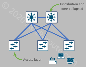
Access tier provides connectivity for the end-users. The access layer requires high-port density capable to deliver Power-over-Ethernet (POE). Switches at the access layer connect to the distribution layer switches and should not be connected to each other. As access switches have direct visibility into devices that connect to them, security access checks, such as 802.1x authentication, and QoS traffic classification are usually performed at this tier.
The distribution tier is responsible for connecting access switches together. Distribution switches usually have high-speed fiber (and less often copper) ports. Traditionally, VLAN’s or subnet’s default gateway functions were provided by distribution layer switches. For this reason, different types of security enforcement, such as inter-VLAN ACLs were implemented on this layer. In modern networks, however, it is also common to see access layer switches configured as default gateways for VLANs.
Core tier connects distribution switches together when there is a requirement to have a 3rd level of the hierarchy. The main responsibility of this layer is to route traffic as fast as possible over multiple redundant paths.
Figure 1 shows a 2-tier design. This architecture comprises only of access and combined distribution-core tiers. It is also referred to as a collapsed core design. The switches on the top perform distribution tier features by providing uplink connectivity for access layer switches. The core feature, or connecting distribution switches together, is implemented by 1 link between these two switches. When the new access layer switches added to the network, it is possible to introduce additional distribution switches to accommodate the expansion.
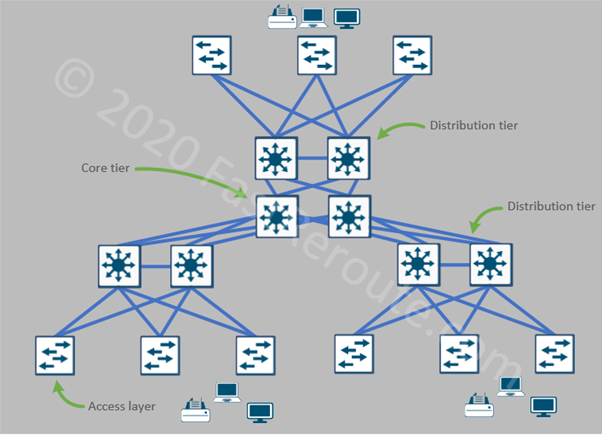
As the number of distribution switches goes up, establishing full-mesh connectivity becomes difficult. Implementing a dedicated set of core devices, so each distribution switch only needs to connect to them can be a good alternative. 3-tier architecture has all 3 layers implemented, as shown in Figure 2.
Data Center Design
Physical topologies
A typical data center consists of multiple server racks connected together. Physical cabling usually follows one of two patterns:
- Top-Of-Rack (TOR)
- End-Of-Row (EOR)
Top-Of-Rack implies that each rack has a single or pair of switches usually installed on the top. The servers are connected to these switches, so all internal cabling stays inside the rack. Top-Of-Rack switches then connect to aggregation switches outside of the rack. End-Of-Row, on the other hand, indicates that only certain racks, for example, first and last rack in each row, have high-port-density switches installed. Servers are then connected using a cross-rack cabling system to these End-Of-Row switches.
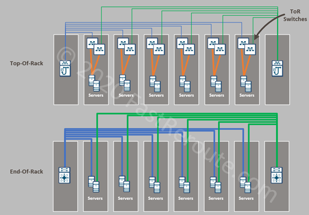
Both topologies have their pros and cons in different scenarios. For example, TOR design requires extra switches to be placed into each rack but has simplified cable management. The TOR switches may be underutilized depending on a number of servers within each rack. EOR topology requires more cables to be installed between racks as port requirements within each rack grow. Racks also should be adjacent to each other, so adding an additional rack may not be as easily accomplished as in TOR design.
Data center design requirements
Data centers host physical and virtual servers. Communication between servers within the data center network produces east-west traffic. It includes traffic between applications and databases, different replication types between servers, and file exchange.
There is a much higher demand for east-west bandwidth in a data center compared to a campus network, which usually doesn’t have much client-to-client communication.
Horizontal scalability, or ability to expand by adding new switches, is another requirement of a data center network. To accommodate an increase in a number of racks, the network must provide ways to connect new switches without affecting available bandwidth for the existing switches.
To address these requirements, the leaf-and-spine design is commonly used to build data centers. This connectivity pattern came from telecommunication circuit switching systems and called the Clos network.
Spine-leaf architecture
The leaf-and-spine topology consists of 2 layers – leaf layer and spine layer. In such topology, every device on one layer connects to every single device on another. No direct links exist between devices located on the same layer. Collectively, network devices on both layers form so-called switch fabric.
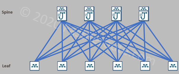
Leaf switches are the access layer of the data center. The servers plug only into leaf switches. The links between leaf and spine switches are point-to-point Layer 3 links and all actively forwarding traffic.
This architecture provides predictable bandwidth between pair of any leaf switches. For example, in figure 4, each leaf switch has 4 uplinks. If each link is 100Gbps, then each leaf switch can provide 400Gbps of uplink bandwidth available to servers connected to it. With 48 10Gbps access ports on leaf switch, the oversubscription ratio is 480/400Gbps or 1.2 to 1. This ratio is preserved even if a number of leaf switches grow, so the network can scale horizontally. If more bandwidth is required, additional spine switches can be added.
Two Cisco data center solutions use leaf-and-spine topology – Cisco ACI and programmable VXLAN EVPN fabrics. Check our article on Cisco ACI foundation.
WAN
WAN or Wide Area Network provides connectivity between offices and remote branches of a company. There are 2 broad categories of WAN networks, which differ by how different sites can communicate with each other, – multi-access and point-to-point networks.
Multi-access vs Point-to-Point WAN
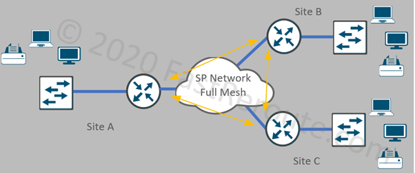
In the multi-access network, the Service Provider (SP) network connects WAN sites in a full-mesh scheme. Depending on the SP infrastructure, this design can provide better performance because of direct site-to-site connectivity. In Figure 5, an example of a multi-access network is shown. All three sites can reach each other directly.
Examples of multi-access networks include:
- Layer 3 MPLS service
- Metro Ethernet E-LAN service (L2 VPLS)
- Older WAN technologies, such as Frame Relay and ATM
VPN-based WANs, such as DMVPN and SD-WAN
Point-to-point connections provide direct connectivity between two sites. Such services have advantages such as simplified bandwidth planning and QoS configuration. It can also provide very high bandwidth when there is dedicated fiber connectivity between sites.
It is still possible to route traffic between spokes via a central hub. For example, in Figure 6 Site B can communicate to Site C by traversing site A. This will increase the load on Site A links and can add delay.
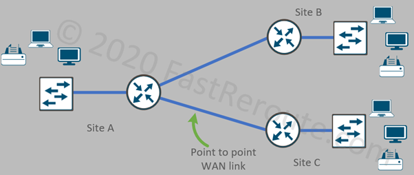
Examples of point-to-point connections include:
- Metro Ethernet E-Line service (L2 MPLS-based or dedicated physical fiber or DWDM)
- VPN-based site-to-site links
Many networks can combine these types of connectivity, for example, large offices can connect over dedicated fiber links to a data center, which has connectivity to the L3 MPLS network connecting smaller sites together.
Layer 2 vs Layer 3 WAN
WAN topologies can also be classified as Layer 2 or Layer 3. The difference between the two is how the service provider network is seen by the customer.
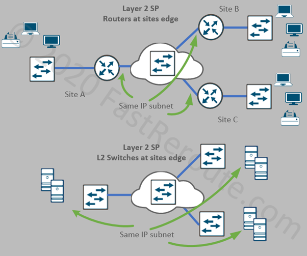
Layer 2 WAN looks like an Ethernet switch in multi-access or as a piece of wire in point-to-point setup. Some Layer 2 services allow 802.1q tagging, so multiple VLANs can be transported over the same link. Metro Ethernet E-LAN (VPLS), E-Line, and direct fiber links are all example of Layer 2 services. Figure 7 shows two variations of using a layer 2 service provider network.
Network on the top part of Figure 7 has edge routers deployed at each site. These routers create Layer 3 boundaries for devices behind them. The WAN-facing interfaces on the routers are in the same VLAN and IP subnet. The benefit of such setup is that a company can use its routing protocol of choice without relying on its support by the service provider.
Network on the bottom part of Figure 7 extends a single Layer 2 subnet to site devices using Layer 2 switches. This topology is rarely used to extend VLANs containing end-user devices due to a lack of practical use. However, it is often used to extend server VLANs when an application requires Layer 2 adjacency across different sites.
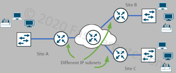
Layer 3 WAN appears like a router managed by the service provider. A site router needs to communicate to the provider network which networks it has behind it. Routing information can be either statically configured by the provider or dynamically exchanged. Service providers may not support routing protocol that is used internally by the customer, for example, EIGRP is rarely supported by Service Providers due to its proprietary nature. L3 MPLS VPN is the most commonly used Layer 3 WAN service.
Small Office/Home Office (SOHO)
SOHO networks are usually designed to meet requirements such as reducing the number of devices and minimizing the complexity of configuration while maintaining enterprise-level security. In many cases, VPN-based solutions over the Internet is the most practical way to provide access to enterprise resources.
Depending on the protocol stack used in the rest of the network, there are 3 available Cisco platforms to choose from:
- Cisco IOS/IOS-XE based
- Cisco SD-WAN
- Meraki MX-based
All three stacks include compact devices with built-in Ethernet switch, built-in WiFi options, and a WAN interface (or two) with 4G backup. Check our article about different SD-WAN platforms.
There are two design options available with SOHO that relate to security.
Centralized Internet vs Local Internet Breakout (Split-tunneling)
Two options are different in what traffic is sent over a VPN tunnel to the corporate VPN gateway.
Centralized option forces all traffic to be sent over the tunnel. This includes Internet traffic which breaks out via the data center, which has a full set of security services available to ensure that there is the same level of security protection available to SOHO users.
With the split-tunnel option, only traffic to the company data center and offices is sent over the tunnel. Internet traffic is not tunneled and sent directly via a local Internet Service Provider. As a result, security inspection must be performed locally by the device.
On-Premises vs Cloud
Data centers traditionally hosted centralized enterprise infrastructure. It is referred to as on-premises infrastructure, which implies that companies have full control over the network, compute, storage, and software components.
As public cloud offerings gained popularity, many organizations shifted their workload out of data centers. Compared to on-premises data centers, public clouds offer very good scalability and rapid deployment with a consumption-based billing model.
In this blog post, we covered different cloud resources from the previous CCNA exam blueprint.
Self-Test Questions
What is the difference between 2-tier and 3-tier network architecture for campus networks?
Both implement functionality of access, distribution, and core layers. 2-tier has distribution and core layers combined in 1. 3-tier has all 3 layers.
Which tier or layer of campus network architecture is responsible for performing 802.1x authentication and QoS classification?
Access layer
Which tier or layer of campus network architecture is responsible for inter-connecting switches that have end-user devices connected to them?
Distribution layer
What communication type is referred to as east-west?
Traffic between servers within the data center
Which devices have interface connected to each other in leaf and spine topology?
Only leaf-to-spine. No leaf-to-leaf and spine-to-spine links exist.
Provide an example of multi-access WAN topology?
MPLS VPN, Metro Ethernet E-LAN, Frame Relay, ATM, DMVPN, and SD-WAN
What are different design options available for Internet breakout for SOHO?
Centralized and local (split-tunnel) Internet breakout