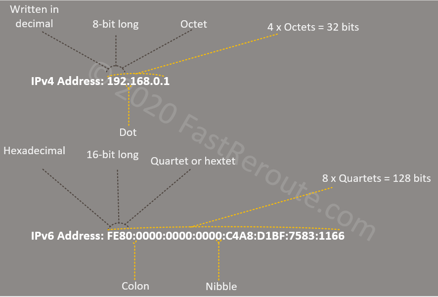
To configure IPv6 in IOS, as with IPv4, addresses need to be assigned to interfaces. You can assign a single link-local address and multiple global addresses. In comparison to IPv4, IPv6 unicast routing is disabled by default and needs to be globally enabled.
First, we will use a command that automatically generates link-local address for the interface.
R01
R01(config)#interface GigabitEthernet 3
R01(config-if)#ipv6 enable
Link-Local Address Configuration
Let’s check what IPv6 address has been allocated by IOS.
R01
R01#show ipv6 interface
GigabitEthernet3 is up, line protocol is up
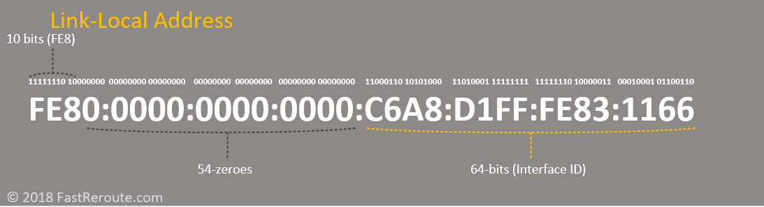
IPv6 is enabled, link-local address is FE80::20C:29FF:FEB8:6296
No Virtual link-local address(es):
No global unicast address is configured
Joined group address(es):
FF02::1
FF02::1:FFB8:6296
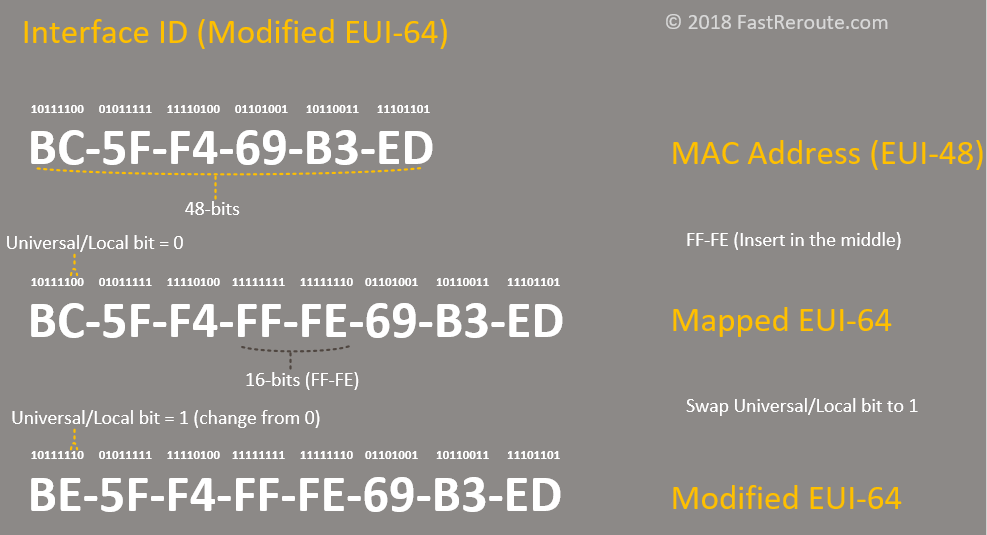
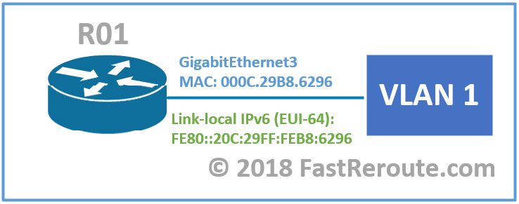
As the listing shows, the link-local address has been automatically assigned. It is derived from the MAC address of the interface displayed in the listing below.
R01
R01#show interface GigabitEthernet3
GigabitEthernet3 is up, line protocol is up
  Hardware is CSR vNIC, address is 000c.29b8.6296 (bia 000c.29b8.6296)
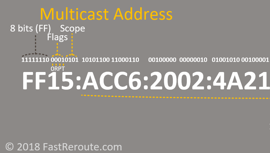
The interface has automatically joined 2 multicast groups – FF02::1, which is the all-nodes address, and solicited-node for this address -FF002::1:FFB8:6296.
See the details on different addresses format and how they are derived in this blog post.
Let’s manually assign the link-local address, so it is not modified EUI-64 based. “ipv6 enable” command can be removed in this case, as its purpose is to just allocate a link-local address. For link-local addresses, no prefix-length needs to be specified, as it has a fixed format.
R01
R01(config)#interface GigabitEthernet 3
R01(config-if)#ipv6 address FE80::1 link-local
Let’s check how the output has changed.
R01
R01#show ipv6 interface
GigabitEthernet3 is up, line protocol is up
  IPv6 is enabled, link-local address is FE80::1
  No Virtual link-local address(es):
  No global unicast address is configured
  Joined group address(es):
    FF02::1
    FF02::1:FF00:1
Notice the new link-local address and solicited-node multicast group addresses.
The next example demonstrates that only one single link-local address is allowed. If a new address is typed in it will overwrite the previous one.
R01
R01(config)#interface GigabitEthernet 3
R01(config-if)#ipv6 address FE80::1 link-local
R01(config-if)#end
R01#show running-config interface Gi3
interface GigabitEthernet3
 no ip address
 ipv6 address FE80::1 link-local
R01(config)#interface GigabitEthernet 3
R01(config-if)#ipv6 address FE80::2 link-local
R01(config-if)#end
R01#show running-config interface Gi3
interface GigabitEthernet3
 no ip address
 ipv6 address FE80::2 link-local
IOS will also prevent typing in an address in the link-local prefix range without a link-local keyword.
R01
R01(config-if)#ipv6 address FE80::1/64
% Link local requires link-local keyword
Addresses in any other than link-local range cannot be used with the keyword.
R01
R01(config-if)#ipv6 address 2001::2 link-local
% Invalid link-local address
Global Unicast Address Configuration
IOS automatically assigns link-local addresses as soon as you configure IPv6 address on the interface. In most cases, you will start your configuration with allocating addresses from global unicast or unique local ranges.
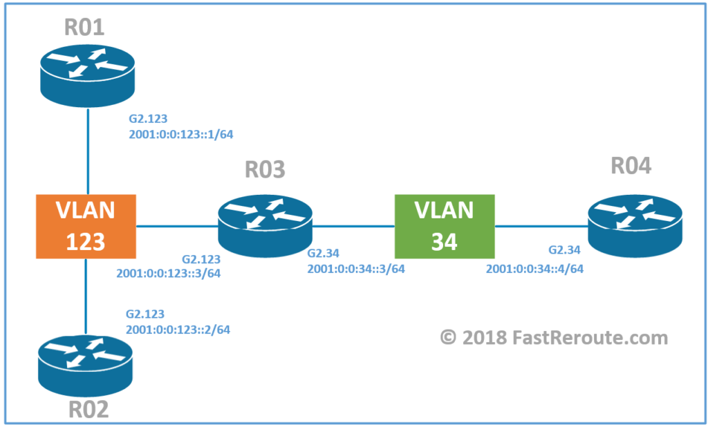
Diagram 2 shows lab topology that we will be using in the next examples.
First let’s configure R1’s interface and verify it’s settings.
R01
R01(config)#interface GigabitEthernet 2.123
R01(config-subif)#encapsulation dot1Q 123
R01(config-subif)#ipv6 address 2001:0:0:123::1/64
R01(config-subif)#end
R01#show ipv6 interface Gi2.123
GigabitEthernet2.123 is up, line protocol is up
  IPv6 is enabled, link-local address is FE80::20C:29FF:FEB8:628C
  No Virtual link-local address(es):
  Global unicast address(es):
    2001:0:0:123::1, subnet is 2001:0:0:123::/64
  Joined group address(es):
    FF02::1
    FF02::1:FF00:1
    FF02::1:FFB8:628C
IOS automatically assigned a link-local address. The global unicast address is now assigned and the interface has joined the corresponding solicited-node multicast group – FF02::1:FF00:1.
The similar configuration is now applied to the remaining routers.
R02
R02(config)#interface GigabitEthernet  2.123
R02(config-subif)#encapsulation dot1q 123
R02(config-subif)#ipv6 address 2001:0:0:123::2/64
R03
R03(config)#interface GigabitEthernet 2.123
R03(config-subif)#encapsulation dot1Q 123
R03(config-subif)#ipv6 address 2001:0:0:123::3/64
R03(config-subif)#interface GigabitEthernet 2.34
R03(config-subif)#encapsulation dot1q 34
R03(config-subif)#ipv6 address 2001:0:0:34::3/64
R04
R04(config)#interface GigabitEthernet 2.34
R04(config-subif)#encapsulation dot1q 34
R04(config-subif)#ipv6 address 2001:0:0:34::4/64
Let’s now test connectivity to confirm that we can reach routers on the same segment. As in IPv4, the ping command recognizes IPv6 address format.
R01
R01#ping 2001:0:0:123::3
Type escape sequence to abort.
Sending 5, 100-byte ICMP Echos to 2001:0:0:123::3, timeout is 2 seconds:
…..
Success rate is 0 percent (0/5)
R01#ping 2001:0:0:123::2
Type escape sequence to abort.
Sending 5, 100-byte ICMP Echos to 2001:0:0:123::2, timeout is 2 seconds:
…..
Success rate is 0 percent (0/5)
The connectivity will not work without enabling ipv6 unicast-routing globally, as it is disabled by default in the version of IOS used in this example. Future versions most likely will have it enabled by default.
R01 (R02, R03, R04)
R01(config)#ipv6 unicast-routing
Now the same subnet reachability is working.
R01#ping 2001:0:0:123::2
Type escape sequence to abort.
Sending 5, 100-byte ICMP Echos to 2001:0:0:123::2, timeout is 2 seconds:
!!!!!
Success rate is 100 percent (5/5), round-trip min/avg/max = 1/1/1 ms

R01#ping 2001:0:0:123::3
Type escape sequence to abort.
Sending 5, 100-byte ICMP Echos to 2001:0:0:123::3, timeout is 2 seconds:
!!!!!
Success rate is 100 percent (5/5), round-trip min/avg/max = 1/1/1 ms
R01#
Similar to the “show ip arp” command that displays IP-to-ARP information, in the IPv6 world, there is a “show ipv6 neighbors” command.
R01
R01#show ipv6 neighbors
IPv6 Address                              Age Link-layer Addr State Interface
2001:0:0:123::2                             0 000c.29ae.3524  REACH Gi2.123
2001:0:0:123::3                             0 000c.29fe.c0ba  REACH Gi2.123
FE80::20C:29FF:FEAE:3524                    1 000c.29ae.3524  STALE Gi2.123
FE80::20C:29FF:FEFE:C0BA                    1 000c.29fe.c0ba  STALE Gi2.123
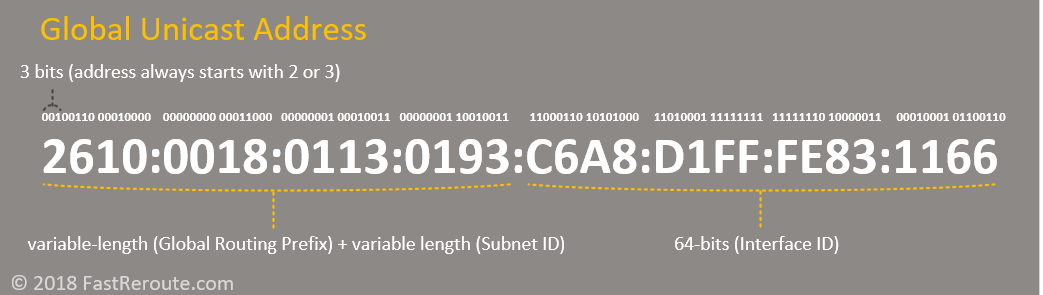
IOS provides another command that can automatically derive the host portion (modified EUI-64) of IPv6 address based on its MAC address. For readability, I’ve assigned the host portion of the address to match the router name. Each interface in IPv6 can have multiple global unicast addresses, so let’s assign the second address to R01.
R01
R01(config)#interface Gi2.123
R01(config-subif)#ipv6 address 2001:0:0:123::/64 eui-64
R01(config-subif)#end
R01#show running-config interface Gi2.123
interface GigabitEthernet2.123
 encapsulation dot1Q 123
 ipv6 address 2001:0:0:123::1/64
 ipv6 address 2001:0:0:123::/64 eui-64
end
R01#show ipv6 interface
GigabitEthernet2.123 is up, line protocol is up
  IPv6 is enabled, link-local address is FE80::20C:29FF:FEB8:628C
  No Virtual link-local address(es):
  Global unicast address(es):
    2001:0:0:123::1, subnet is 2001:0:0:123::/64
    2001::123:20C:29FF:FEB8:628C, subnet is 2001:0:0:123::/64 [EUI]
  Joined group address(es):
    FF02::1
    FF02::2
    FF02::1:FF00:1
    FF02::1:FFB8:628C
Notice that the router now has 2 IP addresses allocated. As both global addresses share the same last 24-bits, they are mapped to the same solicited-node multicast group – FF02::1:FFB8:628C.
Static Routes Configuration
To enable full reachability we will setup static IPv6 routes. R3 knows about both networks, as it has directly attached interfaces in 2001:0:0:123::/64 and 2001:0:0:34::/64. All other routers require a single static route to a remote subnet. First, let’s configure the static route for R1.
R01
R01(config)#ipv6 route 2001:0:0:34::/64 Gi2.123 2001:0:0:123::3
Notice that the route has interface and next-hop information. This type of static route is called a fully specified static route. The next-hop address must be directly attached to the interface. The interface can be omitted, in which case the router will do a lookup to identify the egress interface for the next-hop address. This is called a recursive route lookup. With recursive routes, next-hop is not required to be directly attached.
Let’s check the resulting routing table using the “show ipv6 route” command to confirm that the static route is now present.
R01
R01#show ipv6 route
IPv6 Routing Table - default - 5 entries
Codes: C - Connected, L - Local, S - Static, U - Per-user Static route
       B - BGP, R - RIP, H - NHRP, I1 - ISIS L1
       I2 - ISIS L2, IA - ISIS interarea, IS - ISIS summary, D - EIGRP
       EX - EIGRP external, ND - ND Default, NDp - ND Prefix, DCE - Destination
       NDr - Redirect, RL - RPL, O - OSPF Intra, OI - OSPF Inter
       OE1 - OSPF ext 1, OE2 - OSPF ext 2, ON1 - OSPF NSSA ext 1
       ON2 - OSPF NSSA ext 2, la - LISP alt, lr - LISP site-registrations
       ld - LISP dyn-eid, lA - LISP away, a - Application
S   2001:0:0:34::/64 [1/0]
     via 2001:0:0:123::3, GigabitEthernet2.123
C   2001:0:0:123::/64 [0/0]
     via GigabitEthernet2.123, directly connected
L   2001:0:0:123::1/128 [0/0]
     via GigabitEthernet2.123, receive
L   2001::123:20C:29FF:FEB8:628C/128 [0/0]
     via GigabitEthernet2.123, receive
L   FF00::/8 [0/0]
     via Null0, receive
Reachability to remote subnet now works, as shown in the next listing. As R4 doesn’t have a static route for return traffic at this stage, it is still not reachable.
R01
R01#ping 2001:0:0:34::3
Type escape sequence to abort.
Sending 5, 100-byte ICMP Echos to 2001:0:0:34::3, timeout is 2 seconds:
!!!!!
Success rate is 100 percent (5/5), round-trip min/avg/max = 1/1/5 ms
R01#ping 2001:0:0:34::4
Type escape sequence to abort.
Sending 5, 100-byte ICMP Echos to 2001:0:0:34::4, timeout is 2 seconds:
…..
Success rate is 0 percent (0/5)
As the next step, we will configure all remaining routers. R4 has connectivity only via R3 and is called stub router, so it will have an only default route configured instead of a specific route.
R02
R02(config)#ipv6 route 2001:0:0:34::/64 Gi2.123 2001:0:0:123::3
R04
R04(config)#ipv6 route ::/0 2001:0:0:34::3
Verification Commands
Let’s test that we have now connectivity from R1 to R4. Ping and traceroute commands work in a similar way as in IPv4.
R01
R01#ping 2001:0:0:34::4
Type escape sequence to abort.
Sending 5, 100-byte ICMP Echos to 2001:0:0:34::4, timeout is 2 seconds:
!!!!!
Success rate is 100 percent (5/5), round-trip min/avg/max = 1/1/1 ms
R01(config)#do traceroute 2001:0:0:34::4
Type escape sequence to abort.
Tracing the route to 2001:0:0:34::4
1 2001:0:0:123::3 1 msec 1 msec 1 msec
2 2001:0:0:34::4 1 msec 1 msec 1 msec
To see detailed debug-level information on neighbor discovery we will use the “debug ipv6 nd” command. All debug commands must be used with care in a production environment, as they can cause performance degradation and in some cases can overload the router’s CPU.
In the example below, R01 doesn’t have information about R02’s MAC address. Debug shows that R1 sends Neighbor Solicitation messages and in response gets Neighbor Advertisement message with Link-Local Address (LLA) of R02. Debug also shows that after the exchange of Global Unicast information completed routers exchange link-local IPv6 information.
R01
R01#show ipv6 neighbors
IPv6 Address                              Age Link-layer Addr State Interface
2001:0:0:123::3                             1 000c.29fe.c0ba  STALE Gi2.123
FE80::20C:29FF:FEFE:C0BA                    1 000c.29fe.c0ba  STALE Gi2.123
R01#debug ipv6 nd
  ICMP Neighbor Discovery events debugging is on
  ICMP ND HA events debugging is ON
R01#terminal monitor
R01#
R01#ping 2001:0:0:123::2
Type escape sequence to abort.
Sending 5, 100-byte ICMP Echos to 2001:0:0:123::2, timeout is 2 seconds:
!!!!!
Success rate is 100 percent (5/5), round-trip min/avg/max = 1/3/14 ms
R01#
*Nov 18 00:08:01.516: ICMPv6-ND: (GigabitEthernet2.123,2001:0:0:123::2) DELETE -> INCMP
*Nov 18 00:08:01.519: ICMPv6-ND: (GigabitEthernet2.123,2001:0:0:123::2) Sending NS
*Nov 18 00:08:01.519: ICMPv6-ND: (GigabitEthernet2.123,2001:0:0:123::2) Queued data for resolution
*Nov 18 00:08:01.524: ICMPv6-ND: (GigabitEthernet2.123,2001:0:0:123::2) Received NA from 2001:0:0:123::2
*Nov 18 00:08:01.524: ICMPv6-ND: Validating ND packet options: valid
*Nov 18 00:08:01.524: ICMPv6-ND: (GigabitEthernet2.123,2001:0:0:123::2) LLA 000c.29ae.3524
*Nov 18 00:08:01.524: ICMPv6-ND: (GigabitEthernet2.123,2001:0:0:123::2) INCMP -> REACH
*Nov 18 00:08:01.528: ICMPv6-ND: (GigabitEthernet2.123,2001:0:0:123::1) Received NS from 2001:0:0:123::2
*Nov 18 00:08:01.528: ICMPv6-ND: Validating ND packet options: valid
*Nov 18 00:08:01.528: ICMPv6-ND: (GigabitEthernet2.123,2001:0:0:123::1) Sending NA to 2001:0:0:123::2
*Nov 18 00:08:06.586: ICMPv6-ND: (GigabitEthernet2.123,FE80::20C:29FF:FEB8:628C) Received NS from FE80::20C:29FF:FEAE:3524
*Nov 18 00:08:06.586: ICMPv6-ND: Validating ND packet options: valid
*Nov 18 00:08:06.586: ICMPv6-ND: (GigabitEthernet2.123,FE80::20C:29FF:FEAE:3524) Glean
*Nov 18 00:08:06.586: ICMPv6-ND: (GigabitEthernet2.123,FE80::20C:29FF:FEAE:3524) LLA 000c.29ae.3524
*Nov 18 00:08:06.586: ICMPv6-ND: (GigabitEthernet2.123,FE80::20C:29FF:FEAE:3524) INCMP -> STALE
*Nov 18 00:08:06.587: ICMPv6-ND: (GigabitEthernet2.123,FE80::20C:29FF:FEB8:628C) Sending NA to FE80::20C:29FF:FEAE:3524
*Nov 18 00:08:06.588: ICMPv6-ND: (GigabitEthernet2.123,FE80::20C:29FF:FEAE:3524) STALE -> DELAY
*Nov 18 00:08:11.649: ICMPv6-ND: (GigabitEthernet2.123,FE80::20C:29FF:FEAE:3524) DELAY -> PROBE
*Nov 18 00:08:11.650: ICMPv6-ND: (GigabitEthernet2.123,FE80::20C:29FF:FEAE:3524) Sending NS
*Nov 18 00:08:11.651: ICMPv6-ND: (GigabitEthernet2.123,FE80::20C:29FF:FEAE:3524) Received NA from FE80::20C:29FF:FEAE:3524
*Nov 18 00:08:11.651: ICMPv6-ND: Packet contains no options
*Nov 18 00:08:11.652: ICMPv6-ND: Validating ND packet options: valid
*Nov 18 00:08:11.652: ICMPv6-ND: Packet contains no options
*Nov 18 00:08:11.652: ICMPv6-ND: (GigabitEthernet2.123,FE80::20C:29FF:FEAE:3524) PROBE -> REACH
R01#show ipv6 neighbors
IPv6 Address                              Age Link-layer Addr State Interface
2001:0:0:123::2                             0 000c.29ae.3524  REACH Gi2.123
2001:0:0:123::3                             4 000c.29fe.c0ba  STALE Gi2.123
FE80::20C:29FF:FEAE:3524                    2 000c.29ae.3524  STALE Gi2.123
FE80::20C:29FF:FEFE:C0BA                    4 000c.29fe.c0ba  STALE Gi2.123
Troubleshooting Commands
The other debug command we can use for troubleshooting is the “debug ipv6 packets” command. In the production environment always use access-list based filters to limit the amount of output.
R01
R01#ping 2001:0:0:34::4
Type escape sequence to abort.
Sending 5, 100-byte ICMP Echos to 2001:0:0:34::4, timeout is 2 seconds:
!!!!!
Success rate is 100 percent (5/5), round-trip min/avg/max = 1/1/2 ms
R01#
*Nov 18 00:16:37.609: IPv6-Fwd: Destination lookup for 2001:0:0:34::4 : i/f=GigabitEthernet2.123, nexthop=2001:0:0:123::3
*Nov 18 00:16:37.610: IPv6-Fwd: SAS picked source 2001:0:0:123::1 for 2001:0:0:34::4 (GigabitEthernet2.123)
*Nov 18 00:16:37.610: IPv6-Fwd: nexthop 2001:0:0:123::3,
*Nov 18 00:16:37.610: IPV6: source 2001:0:0:123::1 (local)
*Nov 18 00:16:37.610:       dest 2001:0:0:34::4 (GigabitEthernet2.123)
*Nov 18 00:16:37.610:       traffic class 0, flow 0x0, len 100+0, prot 58, hops 64, originating
*Nov 18 00:16:37.610: IPv6-Fwd: Created tmp mtu cache entry for 2001:0:0:123::1 2001:0:0:34::4 00000000
*Nov 18 00:16:37.610: IPv6-Fwd: L3 injection feature enabled: skipping pak_encap
*Nov 18 00:16:37.611: IPv6-Fwd: Destination lookup for 2001:0:0:123::1 : Local, i/f=GigabitEthernet2.123, nexthop=2001:0:0:123::1
*Nov 18 00:16:37.611: IPV6: source 2001:0:0:34::4 (GigabitEthernet2.123)
*Nov 18 00:16:37.611:       dest 2001:0:0:123::1 (GigabitEthernet2.123)
*Nov 18 00:16:37.611:       traffic class 0, flow 0x0, len 100+18, prot 58, hops 63, forward to ulp
This command produces detailed information on the packet forwarding, including information on which source IPv6 address and the outgoing interface were chosen.