Describe Wireless Principles CCNA
The new CCNA exam now includes topics from the discontinued CCNA Wireless exam. The current blueprint includes the topics listed below.
1.11 Describe wireless principles
- 1.11.a Nonoverlapping Wi-Fi channels
- 1.11.b SSID
- 1.11.c RF
- 1.11.d Encryption
5.9 Describe wireless security protocols (WPA, WPA2, and WPA3)
We will divide these topics into several blog posts – this one will focus on radio fundamental topics and the following posts will cover SSIDs, security protocols, and encryption. The purpose of the series of short articles is to help CCNA candidates with exam preparation.
Frequency
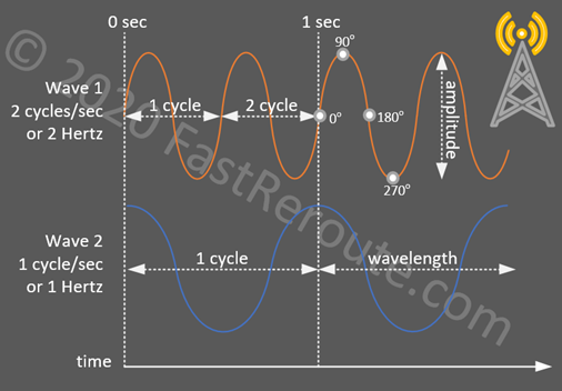
A radio signal is propagated in the form of a wave. One of the most important characteristics of a wave is its frequency. As figure 1 demonstrates, radio wave propagates in repeating cycles, with frequency calculated as a 1 full cycle per second. The frequency of 1 cycle per second is called 1 Hertz. The full cycle also constitutes a wave’s length. Measurement can be performed between any adjacent points of the same phase, for example, in figure 1 the orange wave’s cycle is measured between zero crossings and the blue’s one is between two crests. Lower frequencies have longer wavelengths and can travel further if the same amount of power is applied. For example, to provide some perspective of the actual size, a wave of a frequency of 1 Hertz has a length of 343m or 1125ft, 2.4GHz – 12.5cm or 4.92 inch, 5Ghz – 6cm or 2.36 inch.
Frequencies between 20 kilohertz (kHz) and 300 gigahertz (GHz) are classified as radio frequencies. FM/AM radio, television, DECT phones, and microwave ovens are all operating in the radio frequency range.
802.11 wireless network devices exchange data by transmitting and receiving radio signals in portions of 2 frequency bands – 2.4GHz and 5GHz. Many countries allow unlicensed use of subsets of these frequencies, but there are regulations restricting channel use and maximum transmit power. There are also restrictions on indoor vs outdoor use and even requirements for dynamic switching away from the specific channels when weather radars are discovered. A specific region that the device is certified to work in is called a regulatory domain.
Radio Channels
Radio Channel numbers provide a simple reference to a specific frequency within a band. For example, channel 1 of the 2.4GHz band corresponds to the center frequency of 2412MHz. It is easier to remember channel 1 than its value of 2412MHz. Channel 2 has a center frequency of 2417MHz, or plus additional 5MHz.
Each channel has a range of frequencies to the left and to the right of the center frequency. Channel 1 from our example above has a range of frequencies between 2401 to 2423MHz. The channel’s range is 22MHz, however, their center frequencies are only 5MHz apart. The reason behind this is that the standard uses 5MHz channels for numbering. Devices, on the other hand, use 22MHz or 20MHz-wide channels. We will clarify the difference between 20MHz and 22MHz channels in the following section.
Manual setting of a channel number is usually not required; Wireless LAN Controller will perform required adjustments dynamically to ensure that there are no overlaps between adjacent access points. However, it is important to know the number of available non-overlapping channels when performing wireless network design and site surveys.
DSSS vs OFDM (or 22MHz vs 20MHz)
Direct-Sequence Spread Spectrum (DSSS) is a modulation technique that uses the whole 22-MHz-wide channel to send information. DSSS was introduced with 802.11b standard and 2.4GHz channels frequency ranges were standardized to match its requirement of 22MHz wide-channels. DSSS supports a maximum of 11Mbps.
Orthogonal Frequency-Division Multiplexing (OFDM) uses a different approach by splitting each 20MHz range into multiple smaller sub-channels or carriers. It was introduced with 802.11a for 5GHz and later in 802.11g for use in 2.4GHz. OFDM replaced DSSS as it was capable to provide higher bandwidth. As with DSSS, a single device can transmit at a time, as different sub-carriers in OFDM cannot be used at the same time by multiple transmitters.
Recently released 802.11ax standard or Wi-Fi 6 provides an ability to divide and share these smaller sub-channels between different devices at the same time. The updated OFDM modulation scheme in Wi-Fi 6 is called Orthogonal Frequency-Division Multiplexing Access (OFDMA).
2.4GHz Channels
The table below shows all available 2.4GHz channels. Countries in North America use only the first 11, while the majority of other countries allow the use of 2 additional channels.
| Channel Number | Center Frequency (MHz) |
|---|---|
| 1 | 2412 |
| 2 | 2417 |
| 3 | 2422 |
| 4 | 2427 |
| 5 | 2432 |
| 6 | 2437 |
| 7 | 2442 |
| 8 | 2447 |
| 9 | 2452 |
| 10 | 2457 |
| 11 | 2462 |
| 12 | 2467 |
| 13 | 2472 |
There are only 3 non-overlapping channels in the 2.4GHz range – 1, 6, and 11. There is also channel 14 (2484Mhz), but it can be used only in Japan with 802.11b.
5GHz
5GHz range has several subranges available, which are called Unlicensed National Information Infrastructure (U-NII) bands:
- U-NII-1: 5.150-5.250GHz (4 channels)
- U-NII-2: 5.250-5.350GHz (4 channels)
- U-NII-2 Extended: 5.470-5.725GHz (11 channels)
- U-NII-3: 5.725-5.850GHz (5 channels)
None of the standards for 5GHz don’t support DSSS with its 22MHz channels. Only OFDM and 20MHz-wide channels are used. 802.11n and later 802.11ac allowed bonding of 20MHz channels together to form 40MHz, 80MHz and even 160MHz channels to provide more bandwidth.
The table below shows a larger number of channels that are available in the 5GHz band. Compared to 2.4GHz, the channels don’t overlap, so the whole 2.4GHz range would only take 3 lines if we would remove all overlapping channels.
Numbering is still based on 5MHz increments. Channel 1 starts at 5000MHz, this explains why the first configurable channel number is 36, it corresponds to 5180MHz center frequency (5000 + 36×5).
| Channel Number | Center Frequency (MHz) | Band Designation (US FCC) |
|---|---|---|
| 36 | 5180 | U-NII-1 |
| 40 | 5200 | U-NII-1 |
| 44 | 5220 | U-NII-1 |
| 48 | 5240 | U-NII-1 |
| 52 | 5260 | U-NII-2 |
| 56 | 5280 | U-NII-2 |
| 60 | 5300 | U-NII-2 |
| 64 | 5320 | U-NII-2 |
| 100 | 5500 | U-NII-2 Extended |
| 104 | 5520 | U-NII-2 Extended |
| 108 | 5540 | U-NII-2 Extended |
| 112 | 5560 | U-NII-2 Extended |
| 116 | 5580 | U-NII-2 Extended |
| 120 | 5600 | U-NII-2 Extended |
| 124 | 5620 | U-NII-2 Extended |
| 128 | 5640 | U-NII-2 Extended |
| 132 | 5660 | U-NII-2 Extended |
| 136 | 5680 | U-NII-2 Extended |
| 140 | 5700 | U-NII-2 Extended |
| 149 | 5745 | U-NII-3 |
| 153 | 5765 | U-NII-3 |
| 157 | 5785 | U-NII-3 |
| 161 | 5805 | U-NII-3 |
| 165 | 5825 | U-NII-3 |
The channel availability and power restrictions depend on regulatory domain.
An easy way to check the number of channels that an AP will support in a specific country is based on the following procedure. Navigate to Cisco’s online tool to find out what regulatory domain country is in. Then check the datasheet for the access point. Look for the “Frequency band and 20-MHz operating channels” section of the datasheet. It will list the number of channels supported in different regulatory domains.
Signal Power
Signal power is measured in watts. Radio waves can propagate further when a higher level of transmit power is applied. Amplitude describes signal strength and is a distance between a crest and a trough of the radio wave as shown in figure 1. Typical power levels in wireless networks are measured in milliwatts (1/1000 of a watt). For example, the maximum available transmit power setting for the Catalyst 9130 access point is 200mW in 2.4GHz and 400mW in 5GHz ranges.
Units of Measurement
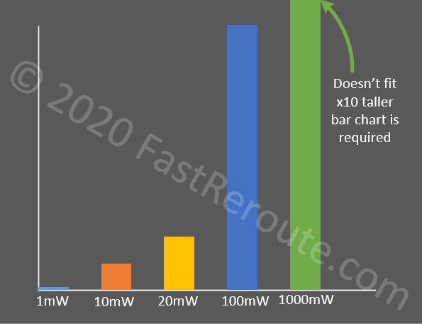
Power levels can also be represented using a relative value in decibels compared to 1mW (dBm). This measurement is based on a logarithmic scale. Imagine that you want to compare 4 power values in milliwatts with values of 1mW, 10mW, 20mW, 100mW, and 1000mW (1 Watt) by drawing them on a bar chart. Due to the large difference between values we cannot fit 1000mW value into the chart.
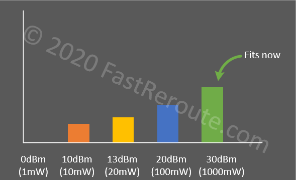
The logarithmic scale allows representing these values evenly by comparing how it changed instead of absolute values. A simplified way to transfer from mW to dB and vice versa is based on adding (or removing) 3dBm when the value in mW doubles (or halves). Similarly, add (or remove) 10dBm when the value in mW increases by ten (or decreases by ten).
Let’s re-map the previous values on a bar chart with a logarithmic scale. The first value of 1mW is the same as our reference value of 1mW in dBm. As there is no change in power value 1mW is translated to 0 dBm. Then there is a tenfold increase to 10mW, which means we need to add 10dBm and the final value is 10dBm. The next value of 20mW is two times larger than 10mW, so we need to add 3dBm which gives us 13dBm.
100mW is tenfold increase from 10mW (10dBm), so we add another 10dBm to get 20dBm. The final value of 1000mW is tenfold increase from 100mW (20dBm); by adding another 10dBm we will get value of 30dBm for 1000mW. The result is shown on figure 3.
dBm can also be negative values to represent values that are smaller than 1mW. For example, -3dBm can be calculated as half of 1mW, which equals to 0.5mW. Refer to this Wikipedia article about logarithmic calculations for more information.
EIRP
Regulations usually specify value called Effective Isotropic Radiated Power (EIRP). EIRP measures actual signal strength as it is emitted by the antenna. For example, transmit power can be low and within allowed limit, however, the antenna can amplify this signal to be higher than the legal threshold.
EIRP represents adjusted signal strength by loss in the cable between an access point and antenna, and gain provided by antenna. It is calculated using the following formula in dBm:
EIRP = transmit power – cable loss + antenna gain
Modulation Techniques
The purpose of a wireless network is to transfer data. We know that there are different parameters that characterize a radio wave. The process of changing radio waves parameters to encode the data in the radio signal is called modulation. The reverse process performed by the receiver is to extract this data back from the signal is called demodulation.
Wireless networks use 2 parameters of radio wave to encode data:
- Phase
- Amplitude
Phase
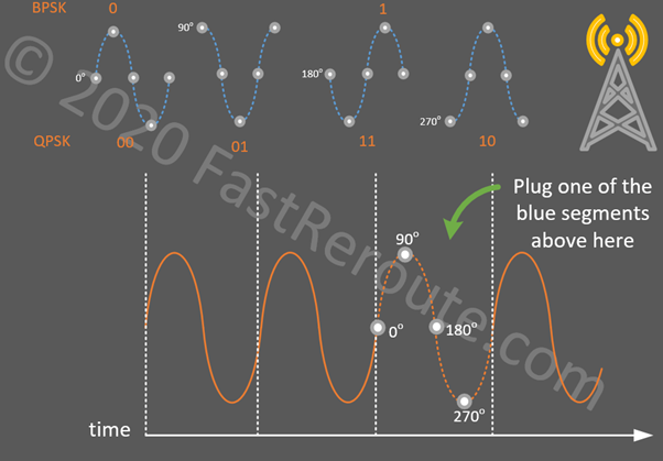
Radio waves follow the same repeating pattern. As shown in figure 4, a phase starts at zero-crossing (0°) and then reaches a peak (90°), then back to zero-crossing (180°) and reaching the trough (270°). Then it repeats after reaching the next zero-crossing (360° or 0°). Phase modulation is based on changing this pattern.
We will discuss 2 types of phase modulations – BPSK and QPSK. Binary Phase Shift Keying (BPSK) can encode a single bit – 0 or 1. As shown in the figure below, the orange wave travels using its normal pattern. No change to a pattern means 0. If the wave is then rotated by 180°, the receiver knows that value 1 is now being transmitted. In figure 4, rotation from 0° to 180° can be visually represented by inserting the third blue pattern into the placeholder. The figure shows a simplified representation of the phase shifts using a single wave cycle. The actual implementation is timer-based and spans several cycles.
Quadrature Phase Shift Keying (QPSK) can carry 2 bits of information – 00, 01, 10, and 11. To do this additional two patterns from our diagram will be used to do 90° or 270° rotation.
Amplitude
The second parameter that can be changed to encode information is amplitude. The transmitter can increase and decrease the power to change the amplitude of the signal. Quadrature Amplitude Modulation (QAM) is a modulation scheme that combines QPSK together with amplitude modulation.
With 4 phase shifts of QPSK 2 bits can be encoded. If at the same time 4 different levels of power can be applied to signal, we will get another 2 bits. This way we have 4 bits in total or 16 possible combinations. This QAM is called 16-QAM.
By increasing the number of available phase shifts and amplitude levels, more information can be packed into the signal. For example, there are 64-QAM (8 phase shifts x 8 amplitudes), 256-QAM (16 x 16).
Self-Test Questions
What is frequency of a radio wave?
Frequency of 1 Hertz is used to describe a wave that oscillates perform one full cycle per second. Frequency of 2.4GHz means that the wave repeats its cycle 2,400,000,000 times per second.
What is DSSS and OFDM; and how are they different?
Both provide a way to encode data to signal. Direct-Sequence Spread Spectrum uses whole channels of 22MHz and was used in earlier 802.11b standard. Orthogonal Frequency-Division Multiplexing subdivides the channel of 20MHz into smaller carrier channels and is used in standards introduced after 802.11b. It also provides higher bandwidth.
How many channels in 2.4GHz band are available in North America and the rest of the world; how many of them don’t overlap?
11 in North America and 13 in the rest of the world. Only 3 non-overlapping channels.
What are 4 bands available within 5GHz range; and what is the maximum number of non-overlapping channels available in each of these 4 bands?
• U-NII-1: 5.150-5.250GHz (4 channels)
• U-NII-2: 5.250-5.350GHz (4 channels)
• U-NII-2 Extended: 5.470-5.725GHz (11 channels)
• U-NII-3: 5.725-5.850GHz (5 channels)
Convert 2mW to dBm; 10mW to dBm?
3dBm; 10dBm
Formula for EIRP calculation?
EIRP = transmit power – cable loss + antenna gain
What are 2 properties of radio waves that are used to encode data in wireless networks?
• Phase
• Amplitude