SNMP Overview
SNMP (Simple Network Management Protocol) defines communication and message format between network management stations and agents.
Every managed network element, such as a router, switch, or host is running a management agent. Its function is to retrieve and modify operational variables’ values as requested by network management stations.
This article contains information on how to enable SNMP agents on different Cisco devices, including IOS, IOS-XE, and NX-OS-based.
SNMPv1/SNMPv2c Configuration
SNMPv1 and SNMPv2c use the same security mechanisms based on communities transmitted in clear-text format. It is still used in some networks, however, SNMPv3 should be used in new deployments.
I will start with SNMPv1 and SNMPv2 configuration first. SNMPv3 configuration will be shown in the later sections.
I’m using 3 different types of devices in this demonstration: Classic IOS, IOS-XE, and NX-OS. The community string is the only required configuration and it is the same for SNMPv1/v2c on our platforms with slightly different keyword options on NX-OS.
Classic IOS (Cisco 1940)
You can specify if the community string is for read-only and read-write access, as well as access-list to control which management stations are allowed to query the device. All options except for community string are optional, with read-only access being the default if none is specified. You can enter more than one community string, as the command doesn’t overwrite previous community value.
C1940(config)#snmp-server community FastRerouteRO ?
   <1-99>       Std IP accesslist allowing access with this community
                string
   <1300-1999>  Expanded IP accesslist allowing access with this
                community string
   WORD         Access-list name
   ipv6         Specify IPv6 Named Access-List
   ro           Read-only access with this community string
   rw           Read-write access with this community string
   view         Restrict this community to a named MIB view

C1940(config)#snmp-server community FastRerouteRO ro
C1940(config)#snmp-server community FastRerouteRW rw
IOS-XE (CSR1000V)
IOS-XE has the same options and keywords as classic IOS:
CSR1000V(config)#snmp-server community FastRerouteRO ?
   <1-99>       Std IP accesslist allowing access with this community
                string
   <1300-1999>  Expanded IP accesslist allowing access with this
                community string
   WORD         Access-list name
   ipv6         Specify IPv6 Named Access-List
   ro           Read-only access with this community string
   rw           Read-write access with this community string
   view         Restrict this community to a named MIB view

CSR1000V(config)#snmp-server community FastRerouteRO ro
CSR1000V(config)#snmp-server community FastRerouteRW rw
NX-OS (Nexus 9000V)
N9K-1(config)# snmp-server community FastRerouteRO ?

   group        Group to which the community belongs
   ro           Read-only access with this community string
   rw           Read-write access with this community string
   use-ipv4acl  Specify IPv4 ACL, the ACL name specified
                after must be IPv4 ACL.
   use-ipv6acl  Specify IPv6 ACL, the ACL name specified
                after must be IPv6 ACL.

N9K-1(config)#snmp-server community FastRerouteRO ro
N9K-1(config)#snmp-server community FastRerouteRW rw
NMS Configuration
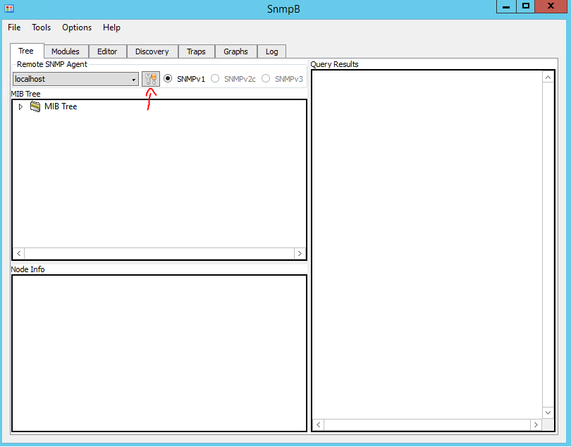
To test the configuration I will be using a great free application called SnmpB (link). For each device, you will require an Agent Profile. Press the Tools button as shown in Figure 1.
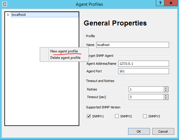
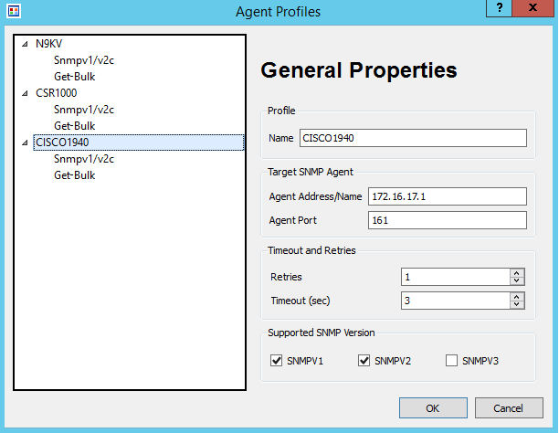
I’ve created a profile for each of the 3 devices. The settings are shown in Figure 3.
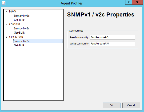
My Cisco 1940 router’s IP address is 172.16.17.1 with the SNMP community of FastRerouteRO as shown in Figure 4.
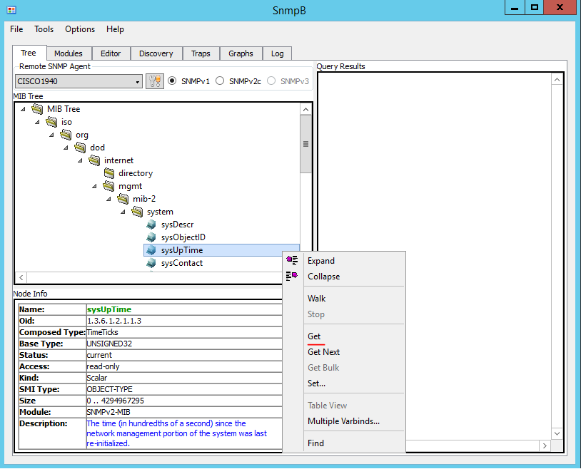
Once profiles are configured, let’s test simple get request for the device uptime. We need to request (using SNMP GET) value of an object that represents device uptime. Any object in SNMP has a unique identifier (OID) and its format and description will be defined in a MIB.
What is MIB and OID?
As per RFC1155 (link) – “Managed objects are accessed via a virtual information store, termed the Management Information Base or MIB… Each type of object (termed an object type) has a name, a syntax, and an encoding. The name is represented uniquely as an OBJECT IDENTIFIER. An OBJECT IDENTIFIER is an administratively assigned name.”
MIB describes a set of objects, including their identifiers, expected reply format, and if values are read-only or can be changed.
For example, MIB-II has the following definition for interface description:
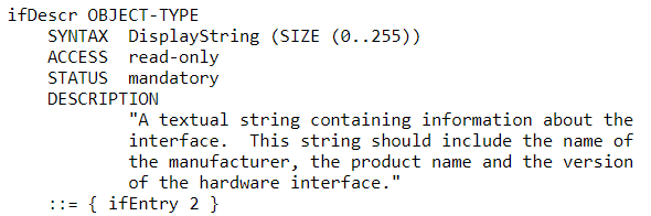
A network device usually supports a standard-based MIB, such as MIB-II (link), as well as vendor-proprietary MIBs. Most NMS have pre-loaded modules for standard MIBs. Import is required to support vendor-specific extensions.
Object Identifier (OID) is written in dotted notation starting with the top-level node. For example, the Internet subtree of Object Identifiers is 1.3.6.1. The object hierarchy has an unlabelled root. Under root, there are 3 allocated child nodes: ccitt (0), iso (1), and joint-iso-ccitt (2).
ISO has a subtree for other organizations org (3), with the child node of (6) assigned to the US Department of Defense (DOD). DoD in turn allocated a node (1) to Internet Activities Board (IAB).
SNMPv2 Testing
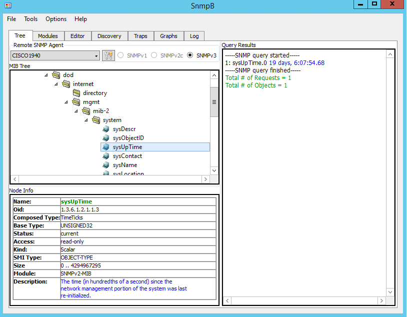
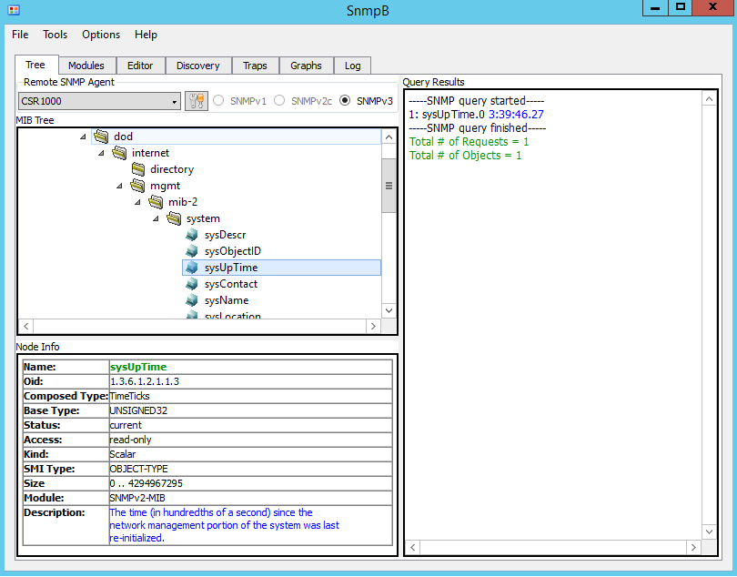
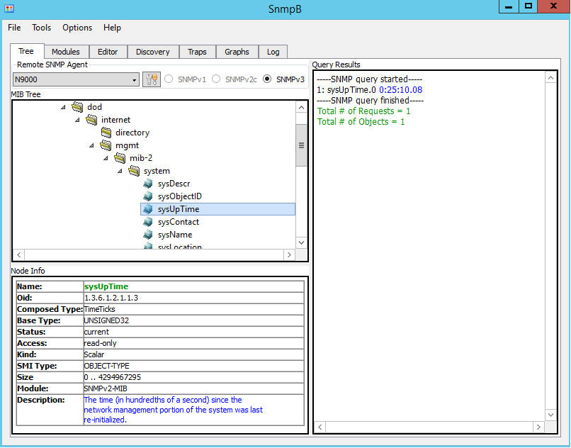
To test – expand the MIB tree and navigate to sysUpTime object (1.3.6.1.2.1.1.3). Note that the Node Info window displays detailed information about the selected object. Right-click on sysUpTime and then select Get.
The Figure 7 shows uptime of the Cisco 1940 router.
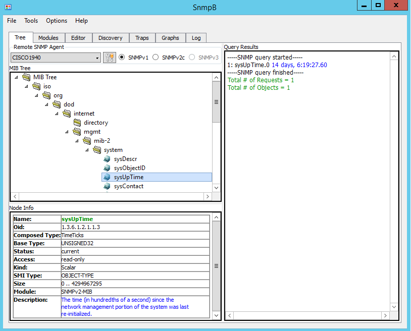
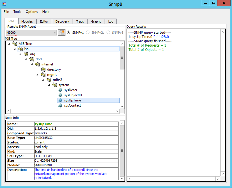
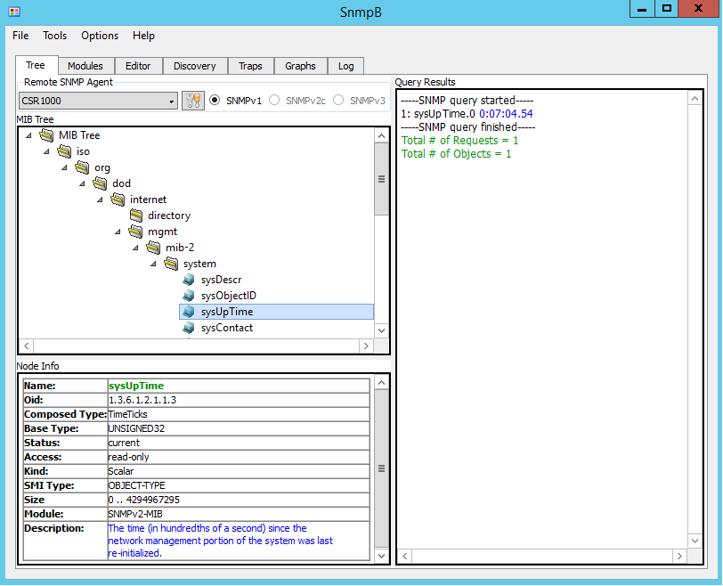
Figure 8 and Figure 9 shows uptime of the Nexus 9000V and CSR. To poll different devices select the corresponding entry in the drop-down box called Remote SNMP Agent.
SNMPv3 Configuration
SNMPv3 defines the User-based Security Model (USM) with the ability to authenticate and encrypt communication between agents and monitoring stations. There are 3 security levels listed below with the weakest first:
• noAuthNoPriv (no authentication or encryption)
• authNoPriv (authentication only)
• authPriv (authentication and encryption)
Minimal configuration of SNMPv3 requires 2 components: Group and User.
Note: There are some interoperability issues between Cisco IOS and IOS-XE devices and SnmpB when AES192 and AES256 used, so AES128 is configured instead in all examples. SNMP debug (debug snmp detail and debug snmp packets) produce the following error with AES192 and AES256:
*Dec 26 02:47:55.691: SNMP: Packet received via UDP from 172.16.17.75 on GigabitEthernet1no such type in ParseType (152) (0x98)
  ParseSequence, Unexpected type: FFFFFFFFFFFFFFFF
  SrParseV3SnmpMessage: ParseSequence:
  SrParseV3SnmpMessage: Failed.
  SrDoSnmp: ASN Parse Error
 *Dec 26 02:47:58.693: SNMP: Packet received via UDP from 172.16.17.75 on GigabitEthernet1no such type in ParseType (152) (0x98)
 ParseSequence, Unexpected type: FFFFFFFFFFFFFFFF
 SrParseV3SnmpMessage: ParseSequence:
 SrParseV3SnmpMessage: Failed.
 SrDoSnmp: ASN Parse Error
Classic IOS (Cisco 1940)
C1940(config)#snmp-server group SNMP-Group v3 ?
   auth    group using the authNoPriv Security Level
   noauth  group using the noAuthNoPriv Security Level
   priv    group using SNMPv3 authPriv security level

C1940(config)#snmp-server group SNMP-Group v3 priv
C1940(config)#snmp-server user SNMP-Admin SNMP-Group v3
              auth sha FastReroute priv aes 128 FastReroute
Note: SNMP users are not stored as part of running or startup configuration, so the second line will not be visible via “show running-config“.
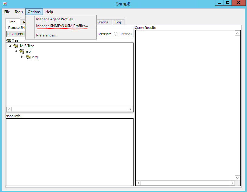
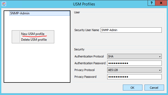
SnmpB requires the configuration of SNMPv3 User. To access the configuration setting click on Options > Manage SNMPv3 USM Profile. Once the USM profile window opens, right-click on a blank space in the list of profiles and select “New USM profile”. I’ve configured username, security parameters to match the ones we configured on the router earlier. See Figures 9 and 10 for details.
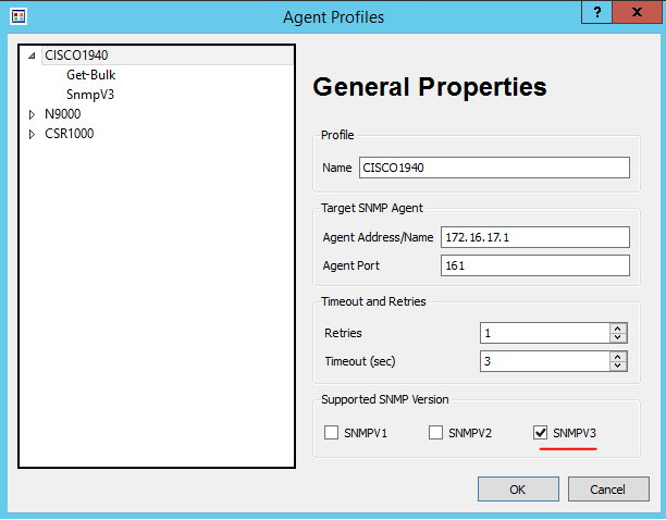
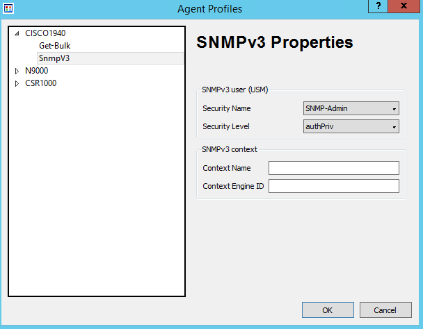
Go back to our device profiles, as shown in the Figure 1. Select SNMPv3 as supported version and choose corresponding Security Name and Levels as shown in Figure 11 and 12.
Let’s try to poll the Cisco 1940 to confirm that we still can access uptime information as shown in Figure 13.
IOS-XE (CSR1000V)
IOS-XE is configured identically as Classic IOS.
CSR1000V(config)#snmp-server group SNMP-Group v3 priv
CSR1000V(config)#snmp-server user SNMP-Admin SNMP-Group v3
                 auth sha FastReroute priv aes 128 FastReroute
NX-OS (Nexus 9000V)
Nexus 9000V minimal configuration is based on a single string, as SNMP groups in NX-OS are replaced by roles for Role-Based Access Control, and by default new users will be assigned network-operator permissions. As a side effect, by default SNMP users will be able to log-in via CLI to the switch with access to all show commands.
Note that there is no group option under SNMP. Use the “role” set of commands, which then can be used as groups in SNMP.
N9K-1(config)# snmp-server ?
   aaa-user           Set duration for which aaa-cached snmp user
                      exists
   community          Set community string and access privs
   contact            Modify sysContact
   context            SNMP context to be mapped
   counter            Configure port counter configuration
   drop               Silently drop unknown v3 user packets
   enable             Enable SNMP Traps
   engineID           Configure a local SNMPv3 engineID
   globalEnforcePriv  Globally enforce privacy for all the users
   host               Specify hosts to receive SNMP notifications
   location           Modify sysLocation
   mib                Mib access parameters
   packetsize         Largest SNMP packet size
   protocol           Snmp protocol operations
   source-interface   Source interface to be used for sending out SNMP
                      notifications
   system-shutdown    Configure snmp-server for reload(2)
   tcp-session        Enable one time authentication for snmp over tcp
                      session.
   user               Define a user who can access the SNMP engine
You can assign users to a group for SNMP-Admin by typing it in straight after the username.
N9K-1(config)# snmp-server user SNMP-Admin ?

   WORD         Group name (ignored for notif target user) (Max Size
                28)
   auth         Authentication parameters for the user
   enforcePriv  Enforce privacy for the user
   use-ipv4acl  Specify IPv4 ACL, the ACL name specified after must be
                IPv4 ACL.
   use-ipv6acl  Specify IPv6 ACL, the ACL name specified after must be
                IPv6 ACL.

N9K-1(config)# snmp-server user SNMP-Admin auth
               sha FastReroute priv aes-128 FastReroute
NX-OS also creates a normal user in addition to the SNMP user. Both users are stored in the running configuration.
N9K-1(config)# show run | incl SNMP

username SNMP-Admin password 5 #password# role network-operator

snmp-server user SNMP-Admin network-operator auth sha
#password# priv aes-128 #password# localizedkey
Let’s test that we can poll N9K using SNMPv3.
SNMP show commands
Classic IOS (Cisco 1940) and IOS-XE (CSR1000V)
Devices keep track of which objects were polled and associated timestamps, as shown in the listings below.
CSR1000V#show snmp stats oid

time-stamp               #of times requested             OID
 03:27:46 UTC Dec 21 2018         6                       sysUpTime
 09:54:49 UTC Dec 18 2018         3                       system.6
 09:54:46 UTC Dec 18 2018         3                       system.4
 09:53:49 UTC Dec 18 2018         2                       system.5
 09:53:49 UTC Dec 18 2018         2                       system.1
 11:27:41 UTC Dec 17 2018         1                       sysOREntry.3
To get the list of SNMP groups use the “show snmp group” command. Note that SNMPv1 and SNMPv2c have groups and as there is no concept of users, they are named as the community name. Also not covered in this article, SNMP views allow restricting access only to specific OIDs or subtrees.
CSR1000V#show snmp group
 groupname: ILMI                 security model:v1
 contextname:                    storage-type: permanent
 readview : *ilmi                writeview: *ilmi
 notifyview:
 row status: active

 groupname: ILMI                 security model:v2c
 contextname:                    storage-type: permanent
 readview : *ilmi                writeview: *ilmi
 notifyview:
 row status: active

 groupname: SNMP-Group          security model:v3 priv
 contextname:                   storage-type: nonvolatile
 readview : v1default           writeview:
 notifyview:
 row status: active

 groupname: FastRerouteRO       security model:v1
 contextname:                   storage-type: permanent
 readview : v1default           writeview:
 notifyview:
 row status: active

 groupname: FastRerouteRO       security model:v2c
 contextname:                   storage-type: permanent
 readview : v1default           writeview:
 notifyview:
 row status: active

 groupname: FastRerouteRW       security model:v1
 contextname:                   storage-type: permanent
 readview : v1default           writeview: v1default
 notifyview:
 row status: active

 groupname: FastRerouteRW       security model:v2c
 contextname:                   storage-type: permanent
 readview : v1default           writeview: v1default
 notifyview:
 row status: active
To get the list of SNMP users use the “show snmp user” command. As users are not displayed in the configuration, this command is the only way to check the SNMP users.
CSR1000V#show snmp user
User name: SNMP-Admin
 Engine ID: 800000090300000C29B86282
 storage-type: nonvolatile        active
 Authentication Protocol: SHA
 Privacy Protocol: AES128
 Group-name: SNMP-Group
NX-OS (Nexus 9000V)
N9K-1# show snmp oid-statistics

 SNMP OID Stats -
 Object ID                                  Min    Max    Avg
 Max Access TS                          Last-polled NMS  Poll Count
                                           (ms)   (ms)   (ms)

 iso.3.6.1.2.1.1.3                           <1     <1     <1
 02:33:25:515 Dec 21 2018             172.16.17.75          1
NX-OS in addition to OID statistics also provides show command to display statistics related to a management station.
N9K-1# show snmp nms-statistics

 - SNMP NMS OID Stats -

 NMS IP Address                              GET    GET    GET    SET
 First Poll                 Last Poll
                                                   NEXT   BULK
 --------------------------------------------------------------------------------
 ----------------------------------------
 172.16.17.75                                  1      0      0      0
 02:33:25:515 Dec 21 2018  02:33:25:515 Dec 21 2018
To get the list of SNMP groups use the “show snmp group” command. Its output is the same as the “show role” command would produce.
N9K-1(config)# show snmp group

Role: aaa-db-admin
   Description: Predefined AAA DB admin, has no cli permissions. Allows RESTful A
 PI

 Rule    Perm    Type        Scope               Entity

 1       permit  read-write

 #some output omitted

 Role: network-admin
   Description: Predefined network admin role has access to all commands
   on the switch

 Rule    Perm    Type        Scope               Entity

 1       permit  read-write
 Role: network-operator
   Description: Predefined network operator role has access to all read
   commands on the switch

 Rule    Perm    Type        Scope               Entity

 1       permit  read

 #some output omitted
To get the list of SNMP users use the “show snmp user” command. Admin users are automatically enabled as SNMP users, as NX-OS implements a single user and role storage.
N9K-1(config)# show snmp user
             SNMP USERS

User Auth Priv(enforce) Groups acl_filter
_  __ _ ___
admin md5 des(no) network-admin
SNMP-Admin sha aes-128(no) network-operator

NOTIFICATION TARGET USERS (configured for sending V3 Inform)

User Auth Priv
_  ___
SNMP debug commands
Classic IOS (Cisco 1940) and IOS-XE (CSR1000V)
Two commands displaying if there is communication with NMS are “debug snmp detail” and “debug snmp packets“. Below is the output generated when a simple SNMP Get request is performed.
CSR1000V#debug snmp detail
 SNMP Detail Debugs debugging is on
CSR1000V#debug snmp packets
 SNMP packet debugging is on
CSR1000V#terminal monitor
 *Dec 26 23:41:59.539: SNMP: Packet received via UDP from 172.16.17.75 on GigabitEthernet1SrParseV3SnmpMessage: Failed..


*Dec 26 23:41:59.539: SNMP: Get request, reqid 1062, errstat 0, erridx 0
  sysUpTime.0 = NULL TYPE/VALUESrDoSnmp: received get pdu
 CheckClassMIBView: all included
 CheckMIBView: OID is in MIB view.

*Dec 26 23:41:59.539: SNMP: Response, reqid 1062, errstat 0, erridx 0
  sysUpTime.0 = 305892
 *Dec 26 23:41:59.540: SNMP: Packet sent via UDP to 172.16.17.75
NX-OS (Nexus 9000V)
In NX-OS use “debug snmp pkt-dump” which is similar to commands shown above for IOS/IOS-XE. Below is the output generated when a simple SNMP Get request is performed.
N9K-1# debug snmp pkt-dump
N9K-1#
 2018 Dec 27 11:45:07.929429 snmpd: 1063.000000:iso.3.6.1.2.1.1.3.0 = NULL  SNMPPKTEND
 2018 Dec 27 11:45:07.929489 snmpd:  SNMPPKTSTRT: 3.000000 160 1063.000000 393237.000000 0.000000 0.000000 0 4 3 3 0    0 remote ip,v4: snmp_54789_172.16.17.75 \200 11  0 \200 11 SNMP-Admin 10 0 0 0x11e950d4 90
 2018 Dec 27 11:45:07.929560 snmpd: 1063.000000:iso.3.6.1.2.1.1.3.0 = Timeticks: (339820) 0:56:38.20  SNMPPKTEND
 2018 Dec 27 11:45:07.929577 snmpd:  SNMPPKTSTRT: 3.000000 162 1063.000000 393237.000000 0.000000 0.000000 0 4 3 3 0    0 remote ip,v4: snmp_54789_172.16.17.75 \200 11  0 \200 11 SNMP-Admin 10 0 0 0x11e950d4 90