Explain Role and Function of Network Components – Part 1

This blog post provides an overview of different network components and their role and functions. The article’s target audience is CCNA candidates and students looking for introductory information about computer network components. In this first post of the 3-article series, we will start by exploring the functions of endpoints and servers. Then the section about LAN switches will follow focusing on the difference between Layer 2 and Layer 3 switch operation.

Endpoints and Servers

The purpose of the infrastructure that the network devices create is to connect endpoints, such as computers, laptops, mobile and IP phones, and servers. A typical endpoint usually runs client applications, for example, a web browser and mail client that interact with the users. These network-enabled applications use services provided by network protocol stacks, drivers, and hardware components.

Out of all network components, endpoints have the most obvious role – they generate useful network payloads, such as digitized voice or Excel spreadsheets that are being transmitted over the network. And their function is to interact with a user, follow specific standards and protocols, so the transmitted data can be decoded on the receiving side of the connection.

Endpoints have an Operating System, which interacts with physical hardware using drivers. Operating System manages networking stack and provides APIs, so the application developers can work with the network without having to program low-level hardware components.

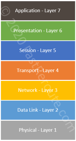
The most common type of wired connectivity is Ethernet, which is described by multiple IEEE 802.3 standards. Wireless communication is defined by IEEE 802.11 standards. Both types of connections use the same addressing, which is used to send frames between devices on the same network. Usually, this type of communication is referred to as Layers 1 and Layer 2 operations of the 7-layer OSI reference model. Layer 1 deals with physical specifications, such as electronic signals transferred over the wire. Layer 2 uses services provided by Layer 1 and is responsible for data framing and addressing.

Figure 1. OSI 7-Layer Model

Almost all OS stacks support and prefer one of two versions of IP protocol (IPv4 or IPv6). Each endpoint is assigned with an IP address that is used for addressing when a packet needs to be transmitted over multiple physical networks. This type of communication is referred to as Layer 3 connectivity.

There are two IP protocols operating on Layer 4 – Transport Control Protocol (TCP) and User Datagram Protocol (UDP). A connection or flow between two devices is identified by source and destination port (both TCP and UDP use concept of ports). Connection is usually initiated by a client. Servers wait for new connections to be established by listening on a specific port. TCP port 0 to 1023 are well-known ports allocated to the specific applications. Client-side uses dynamically allocated ports.

Layer 2 Switches

CCNA blueprint doesn’t include Ethernet hubs, as there are now fully replaced by the switches. However, it is still helpful to understand the way a hub operates to understand the benefits that Layer 2 switches provide.

Early Ethernet network technologies were either bus or star topology-based. Bus topology would have end devices sequentially connected to each other with a coaxial cable. A hub allowed building a star-like topology where all UTP (twisted pair) cabling would terminate in a single location with the hub being the center of the star. In both cases, the network was shared medium and each machine must first listen if there is an active transmission on the network before sending any traffic on its own.

If 2 devices send traffic at the same time a collision occurs and both devices pause for some random amount of time before trying again. Such mode of operation is called CSMA/CD (Carrier-Sense Multiple Access with Collision Detection).

Hubs create a collision domain by re-sending traffic to every port except the ingress one, which makes total available bandwidth smaller as the number of devices increases.

Layer 2 switch solves the issue of sending traffic to all ports by inspecting incoming traffic and learning addresses of devices behind each port, so it can then send unicast traffic through the correct port, as opposed to flooding. BUM traffic (Broadcast, Unknown Unicast and Multicast) is still sent out of all ports. Switches also can store some amount of traffic in its buffers if there is more traffic to be sent than the port’s available bandwidth.

Endpoints connected to a switched port don’t need to listen if other hosts on the network are sending traffic and can send data at any time. Such ports are operating in full-duplex and will not experience collisions as the devices connected to hub ports.

Ethernet Layer 2 switches are usually placed at the access level with the end-users, phones, and printers connected to them. Most of the Cisco Ethernet switches have 24 or 48 ports.

In the topology shown below, the switch uses only hardware MAC address information to forward frames. Both PCs and servers will also have Layer 3 address, such as IP or IPv6, however, for a Layer 2 switch operation, this information is not being processed for traffic forwarding.

Figure 2. Layer 2 Switch Operation

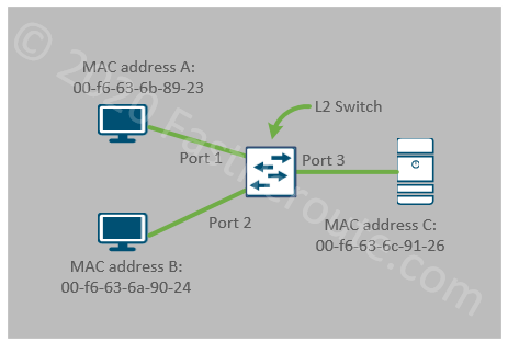
Layer 2 switches provide connectivity between hosts on Layer 2 with connected endpoints sharing the same broadcast domain and IP subnet. All 3 devices in the figure above are in the same VLAN and can communicate with each other. The switch will maintain a table of MAC address to port mappings.

Layer 2 switch can create broadcast domain boundaries by placing a group of ports into different VLANs, but it cannot provide communication between these domains. In the sample topology below A and B (ports 1 and 2) are in VLAN 10 and communicate with each other. C and D (ports 3 and 4) are in VLAN 20 and can also communicate with each other. There is no communication between VLAN 10 and VLAN 20 possible with only Layer 2 switch.

Figure 3. Layer 2 Switch Operation - VLANs
Figure 3. Layer 2 Switch Operation – VLANs

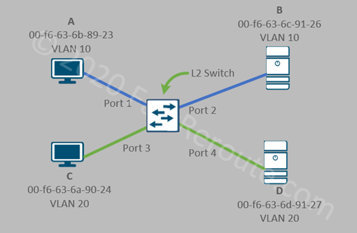
A layer 3 device is required to perform this function. In the campus network, it is the responsibility of a Layer 3 switches to provide connectivity between VLANs.

Self-test question: What are the functions of Layer 2 switch?
• Provide wired full-duplex connectivity to the end users and phones

• Divide collision domains. Each port is a separate collision domain

• Ability to create isolated broadcast domains with VLANs

Layer 3 Switches

Layer 3 switches traditionally were placed at the distribution level, however, in modern networks routed access becomes more common. Almost all current Cisco switching platforms can perform inter-VLAN routing and can act as Layer 3 switches on the network. Therefore, the distinction between Layer 2 and Layer 3 switches is in their configuration, not the specific model.

Layer 3 switching is essentially IP routing or packet forwarding based on Layer 3 addressing. Modern Layer 3 switches perform routing in hardware and can provide very high throughput comparable to Layer 2 switching. However, Layer 3 switches have a smaller feature sets when comparing to routers, which can usually be found at the WAN edge of the network.

To perform its operation Layer 3 switch must have either a logical interface in VLANs that it routes for or a physical interface with IP address assigned to it.

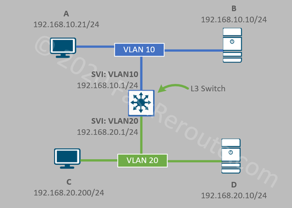
Switched Virtual Interface (SVI) is a logical interface named after VLAN it is connected to. It has an IP address allocated to it, to provide routing for this VLAN clients. As shown in the diagram below, Layer 3 switch has 2 SVIs – VLAN10 and VLAN20. Notice that now devices are shown with IPv4 addresses allocated to them instead of hardware MAC addresses, as this is the information relevant for Layer 3 switch operation.

Layer 2 operations are still performed in exactly the same way as described in the Layer 2 switch section. For example, if the workstation A sends a packet to the server B, no routing is required and Layer 2 forwarding is used to deliver the frame.

If host A will try to communicate to host D inter-VLAN routing will be performed by the switch, which will involve two-step process – Layer 2 communication between host A and switch VLAN 10 SVI; and another one between switch’s VLAN 20 SVI and the server D.

Figure 4. Layer 3 Switch Operation – SVIs

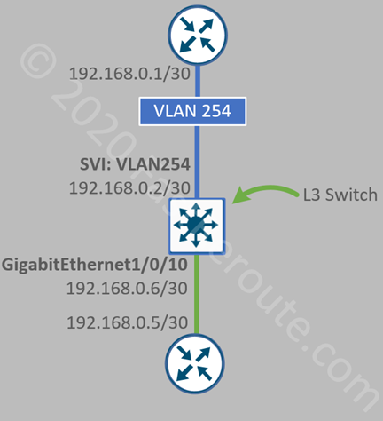
Physical IP interfaces are usually used on transit segments. Consider the topology shown in the next diagram. Switch connects to two routers. A point-to-point subnet of /30, which can accommodate only 2 hosts, has been to allocate to each of the connections. We now have two configuration options. The top router is connected via Layer 2 port which is a member of VLAN 254. We then create an SVI on the L3 switch for VLAN 254. As we assigned only a single Layer 2 port to this VLAN, the connection is point-to-point. This is similar to the previous example.

The second option is to configure the physical port, in our case, it is GigabitEthernet1/0/10 as Layer 3 port. We don’t have to consume a VLAN ID and configuration is contained within a single interface.

Figure 5. Layer 3 Switch Operation – L3 Interfaces
Self-test question: What are the functions of Layer 3 switch?
• Can perform all functions of Layer 2 switch

• Performs high-speed routing between VLANs

• Traditionally deployed at distribution layer of the campus network

• Can be deployed at the access layer when routed access design is used

In the second part of these series of articles, we will discuss the operation of another type of LAN device which provides connectivity to the wireless clients – Access Points. Wireless LAN Controller functions will also be presented.

The third part of this series will be dedicated to devices that are usually found at the edge of the network, such as routers, firewalls, and IPSs.

DNA Center is introduced in its own article.

Reference materials

Cisco SD-Access

Collapsed core and three-tier architecture

Cisco Clock Timezone Configuration

This article provides sample Cisco configuration commands for popular cities using “clock timezone” and “clock summer-time” commands. It also aggregates information about different time zones and their daylight saving dates.

Many services are dependent on the clock and time zone configuration on Cisco devices. Services such as certificate validity checks, logging are the obvious ones. The other examples include time-based ACLs or scheduled tasks that can cause outages during the daylight saving changes. The daylight savings rules are also changing time after time.

Time Zones and Daylight Settings

The time zone represents an area or region that observes the same time. Coordinated Universal Time (UTC) is the reference time. Time zones are expressed as an offset from it. Offset can be either negative or positive represented in a number of hours and in some cases in minutes.

Some regions observe daylight savings time when clocks are adjusted twice a year so there is an extra hour of daylight in the evening during summer. There are more daylight hours in summer than during winter. The difference is more noticeable when moving away from the equator. The adjustment is done in spring by moving clocks forward (spring forward) and then reversed in autumn by moving clocks back (fall back). Note that summer starts in December in some of the countries in the Southern hemisphere.

Time Configuration on Cisco devices

We recommend using NTP to ensure that time is accurately synchronized. NTP server sends time information in UTC, so it is important to set the correct time zone.

If manual clock settings are in use, the router assumes that the time is specified in the router’s local time zone, which is UTC by default. Therefore, the time zone settings should be configured before setting the clock manually, as otherwise, it will need to be re-adjusted after the router applies time zone configuration.

The following paragraphs show how to configure the correct time zone and daylight savings settings on the device.

To specify time zone and daylight settings two commands are used:

R1(config)#clock ?        
   summer-time     Configure summer (daylight savings) time
   timezone        Configure time zone

Time zone configuration requires only 2 parameters:

clock timezone zone hours-offset [minutes-offset]

Summer-time configuration can be either recurring or date-specific:

clock summer-time zone recurring [week day month hh:mm week day month hh:mm [offset]]
 clock summer-time zone date date month year hh:mm date month year hh:mm [offset]

Time Configuration on Cisco devices

The easiest way to lookup information is by navigating to the timeanddate.com website and browsing to the world clock page.

Then find the city name and click on it. Select the Time Zone button and it will display abbreviation and up-to-date information on when DST starts.

Below are the configuration samples for some of the popular cities with updated daylight information as of March 2020.

North America

CityCommand
Honolulu, US# Hawaii Standard Time
clock timezone HST -10
Vancouver, Canada# Pacific Standard Time
clock timezone PST -8

# Pacific Daylight Time
clock summer-time PDT recurring 2 Sun Mar 2:00 1 Sun Nov 2:00
Los Angeles, US
San Francisco, US
Las Vegas, US
Seattle, US
# Pacific Standard Time
clock timezone PST -8

# Pacific Daylight Time
clock summer-time PDT recurring 2 Sun Mar 2:00 1 Sun Nov 2:00
Mexico City, Mexico# Central Standard Time
clock timezone CST -6

# Central Daylight Time
clock summer-time CDT recurring 1 Sun Apr 2:00 last Sun Oct 2:00
Denver, US# Mountain Standard Time
clock timezone MST -7

# Mountain Daylight Time
clock summer-time MDT recurring 2 Sun Mar 2:00 1 Sun Nov 2:00
Cancun, Mexico# Eastern Standard Time
clock timezone EST -5
Panama, Panama# Eastern Standard Time
clock timezone EST -5
New Orleans, US
Kansas City, US
Austin, US
Dallas, US
Milwaukee, US
# Central Standard Time
clock timezone CST -6

# Central Daylight Time
clock summer-time CDT recurring 2 Sun Mar 2:00 1 Sun Nov 2:00
Ottawa, Canada
Ontario, Canada
Montreal, Canada
Quebec, Canada
# Eastern Standard Time
clock timezone EST -5

# Eastern Daylight Time
clock summer-time EDT recurring 2 Sun Mar 2:00 1 Sun Nov 2:00
Havana, Cuba# Cuba Standard Time
clock timezone CST -5

# Cuba Daylight Time
clock summer-time CDT recurring 2 Sun Mar 2:00 1 Sun Nov 1:00
Washington DC, US
Florida, US
Tampa, US
Atlanta, US
Indianapolis, US
Louisville, US
Baltimore, US
Boston, US
Michigan, US
New York, US
Philadelphia, US
Pittsburgh, US
Portsmouth, US
# Eastern Standard Time
clock timezone EST -5

# Eastern Daylight Time
clock summer-time EDT recurring 2 Sun Mar 2:00 1 Sun Nov 2:00
Halifax, Canada# Atlantic Standard Time
clock timezone AST -4

# Atlantic Daylight Time
clock summer-time ADT recurring 2 Sun Mar 2:00 1 Sun Nov 2:00

Table 1. North America Cities and Cisco Timezone Configuration Commands

South America

CityCommand
Bogota, Colombia# Colombia Time
clock timezone COT -5
Lima, Peru# Peru Time
clock timezone PET -5
Santa Cruz, Bolivia# Bolivia Time
clock timezone BOT -4
Caracas, Venezuela# Venezuelan Standard Time
clock timezone VET -4
Buenos Aires, Argentina
Santa Fe, Argentina
# Argentina Time
clock timezone ART -3
Brasilia, Brazil
Rio de Janeiro, Brazil
Sao Paulo, Brazil
# Brasilia Time
clock timezone BRT -3
Asuncion, Paraguay# Paraguay Time
clock timezone PYT -4

# Paraguay Summer Time
clock summer-time PYST recurring 1 Sun Oct 0:00 last Sun Oct 0:00
Montevideo, Uruguay# Uruguay Time
clock timezone UYT -3

Table 2. South America Cities and Cisco Timezone Configuration Commands

Europe

CityCommand
Reykjavik, Iceland# Greenwich Mean Time
clock timezone GMT
Dublin, Ireland# Greenwich Mean Time
clock timezone GMT

# Irish Standard Time (Daylight saving)
clock summer-time IST recurring last Sun Mar 1:00 last Sun Oct 2:00
Lisbon, Portugal
Porto, Portugal
# Western European Time
clock timezone WET

# Western European Summer Time
clock summer-time WEST recurring last Sun Mar 1:00 last Sun Oct 2:00
Birmingham, UK
Bristol, UK
Leeds, UK
Liverpool, UK
London, UK
Manchester, UK
Belfast, UK
Edinburgh, UK
Glasgow, UK
# Greenwich Mean Time
clock timezone GMT

# British Summer Time
clock summer-time BST recurring last Sun Mar 1:00 last Sun Oct 2:00
Tirana, Albania
Salzburg, Austria
Vienna, Austria
Brussels, Belgium
Sarajevo, Bosnia-Herzegovina
Zagreb, Croatia
Prague, Czechia
Copenhagen, Denmark
Strasbourg, France
Paris, France
Versailles, France
Toulouse, France
Marseille, France
Stuttgart, Germany
Munich, Germany
Berlin, Germany
Hamburg, Germany
Frankfurt, Germany
Hannover, Germany
Dortmund, Germany
Leipzig, Germany
Gibraltar, Gibraltar
Budapest, Hungary
Naples, Italy
Turin, Italy
Venice, Italy
Amsterdam, Netherlands
The Hague, Netherlands
Oslo, Norway
Krakow, Poland
Warsaw, Poland
Belgrade, Serbia
Ljubljana, Slovenia
Barcelona, Spain
Ibiza, Spain
Madrid, Spain
Stockholm, Sweden
Bern, Switzerland
Geneva, Switzerland
Lugano, Switzerland
Vatican City, Vatican City State
# Central European Time
clock timezone CET +1

# Central European Summer Time
clock summer-time CEST recurring last Sun Mar 2:00 last Sun Oct 3:00
Plovdiv, Bulgaria
Sofia, Bulgaria
Tallinn, Estonia
Helsinki, Finland
Athens, Greece
Riga, Latvia
Vilnius, Lithuania
Bucharest, Romania
Kyiv, Ukraine
Odesa, Ukraine
# Eastern European Time
clock timezone EET +2

# Eastern European Summer Time
clock summer-time EEST recurring last Sun Mar 3:00 last Sun Oct 4:00
Kaliningrad, Russia# Eastern European Time
clock timezone EET +2
Minsk, Belarus
Bryansk, Russia
Sochi, Russia
Moscow, Russia
Saint-Petersburg, Russia
# Moscow Standard Time
clock timezone MSK +3

Table 3. Europe Cities and Cisco Timezone Configuration Commands

Asia

CityCommand
Jerusalem, Israel
Tel Aviv, Israel
# Israel Standard Time
clock timezone IST +2

# Israel Daylight Time
clock summer-time IDT recurring last Sun Mar 2:00 last Sun Oct 2:00
Beirut, Lebanon# Eastern European Time
clock timezone EET +2

# Eastern European Summer Time
clock summer-time EEST recurring last Sun Mar 0:00 last Sun Oct 0:00
Baghdad, Iraq
Kuwait City, Kuwait
Doha, Qatar
Riyadh, Saudi Arabia
# Arabia Standard Time
clock timezone AST +3
Istanbul, Turkey# Turkey Time
clock timezone TRT +3
Tbilisi, Georgia# Georgia Standard Time
clock timezone GET +4
Yerevan, Armenia# Armenia Time
clock timezone AMT +4
Baku, Azerbaijan# Azerbaijan Time
clock timezone AZT +4
Dubai, United Arab Emirates# Gulf Standard Time
clock timezone GST +4
Kabul, Afghanistan# Afghanistan Time
clock timezone AFT +4 30
Tehran, Iran# Iran Standard Time
clock timezone IRST +3 30

# Iran Daylight Time 2020
clock summer-time IRDT date 21 Mar 2020 0:00 21 Sep 2020 0:00
# Iran Daylight Time 2021-2023
clock summer-time IRDT date 22 Mar 2021 0:00 22 Sep 2021 0:00
clock summer-time IRDT date 22 Mar 2022 0:00 22 Sep 2022 0:00
clock summer-time IRDT date 22 Mar 2023 0:00 22 Sep 2023 0:00
Islamabad, Pakistan
Karachi, Pakistan
Lahore, Pakistan
# Pakistan Standard Time
clock timezone PKT +5
Ufa, Russia
Chelyabinsk, Russia
Yekaterinburg, Russia
# Yekaterinburg Time
clock timezone YEKT +5
Dushanbe, Tajikistan# Tajikistan Time
clock timezone TJT +5
Ashgabat, Turkmenistan# Turkmenistan Time
clock timezone TMT +5
Tashkent, Uzbekistan# Uzbekistan Time
clock timezone UZT +5
Delhi, India
New Delhi, India
Bangalore, India
Mumbai, India
Kolkata, India
Colombo, Sri Lanka
# India Standard Time
clock timezone IST +5 30
Kathmandu, Nepal# Nepal Time
clock timezone NPT +5 45
Dhaka, Bangladesh# Bangladesh Standard Time
clock timezone BST +6
Almaty, Kazakhstan
Nursultan, Kazakhstan
# Alma-Ata Time
clock timezone ALMT +6
Bishkek, Kyrgyzstan# Kyrgyzstan Time
clock timezone KGT +6
Omsk, Russia# Omsk Standard Time
clock timezone OMST +6
Phnom Penh, Cambodia
Hanoi, Vietnam
Ho Chi Minh, Vietnam
# Indochina Time
clock timezone ICT +7
Jakarta, Indonesia# Western Indonesian Time
clock timezone WIB +7
Novosibirsk, Russia# Novosibirsk Time
clock timezone NOVT +7
Beijing, China
Guangzhou, China
Shenzhen, China
Harbin, China
Nanjing, China
Shanghai, China
Chengdu, China
Lhasa, China
Hangzhou, China
Taipei, Taiwan
# China Standard Time
clock timezone CST +8
Hong Kong, Hong Kong# Hong Kong Time
clock timezone HKT +8
Kuala Lumpur, Malaysia# Malaysia Time
clock timezone MYT +8
Manila, Philippines# Philippine Time
clock timezone PHST +8
Irkutsk, Russia# Irkutsk Time
clock timezone IRKT +8
Singapore, Singapore# Singapore Time
clock timezone SGT +8
Kyoto, Japan
Osaka, Japan
Sapporo, Japan
Tokyo, Japan
Yokohama, Japan
# Japan Standard Time
clock timezone JST +9
Chita, Russia
Yakutsk, Russia
# Yakutsk Time
clock timezone YAKT +9
Busan, South Korea
Daegu, South Korea
Incheon, South Korea
Seoul, South Korea
# Korea Standard Time
clock timezone KST +9
Vladivostok, Russia# Vladivostok Time
clock timezone VLAT +10

Table 4. Asia Cities and Cisco Timezone Configuration Commands

Africa

CityCommand
Bissau, Guinea-Bissau
Monrovia, Liberia
Timbuktu, Mali
Dakar, Senegal
# Greenwich Mean Time
clock timezone GMT
Algiers, Algeria
Constantine, Algeria
Tunis, Tunisia
# Central European Time
clock timezone CET +1
Kinshasa, Congo
Lagos, Nigeria
# West Africa Time
clock timezone WAT +1
Casablanca, Morocco
Marrakech, Morocco
Tangier, Morocco
# Western European Summer Time
clock timezone WEST +1
Alexandria, Egypt
Cairo, Egypt
Tobruk, Libya
Tripoli, Libya
# Eastern European Time
clock timezone EET +2
Cape Town, South Africa
Johannesburg, South Africa
Pretoria, South Africa
# South Africa Standard Time
clock timezone SAST +2
Khartoum, Sudan
Port Sudan, Sudan
# Central Africa Time
clock timezone CAT +2
Addis Ababa, Ethiopia
Mombasa, Kenya
Mogadishu, Somalia
Zanzibar City, Tanzania
# Eastern Africa Time
clock timezone EAT +3

Table 5. Africa Cities and Cisco Timezone Configuration Commands

Australia/Pacific

CityCommand
Perth, Australia# Australian Western Standard Time
clock timezone AWST +8
Darwin, Australia# Australian Central Standard Time
clock timezone ACST +9 30

Brisbane, Australia
Cairns, Australia
# Australian Eastern Standard Time
clock timezone AEST +10
Adelaide, Australia# Australian Central Standard Time
clock timezone ACST +9 30

# Australian Central Daylight Time
clock summer-time ACDT recurring 1 Sun Oct 2:00 1 Sun Apr 3:00
Canberra, Australia
Sydney, Australia
Hobart, Australia
Melbourne, Australia
# Australian Eastern Standard Time
clock timezone AEST +10

# Australian Eastern Daylight Time
clock summer-time AEDT recurring 1 Sun Oct 2:00 1 Sun Apr 3:00
Noumea, New Caledonia# New Caledonia Time
clock timezone NCT +11
Port Vila, Vanuatu# Vanuatu Time
clock timezone VUT +11
Auckland, New Zealand
Christchurch, New Zealand
Wellington, New Zealand
# New Zealand Standard Time
clock timezone NZST +12

# New Zealand Daylight Time
clock summer-time NZDT recurring last Sun Sep 2:00 1 Sun Apr 3:00

Table 6. Australia/Pacific Cities and Cisco Timezone Configuration Commands

Reference Information

Alphabetically sorted list of time zone abbreviations:

https://www.timeanddate.com/time/zones/

IANA supports the time zone database (https://www.iana.org/time-zones) and at the time of this blog post writing the latest one is 2019c release. To receive updates on time zone database updates, you can subscribe to the IANA’s mailing list (https://mm.icann.org/mailman/listinfo/tz-announce).

Cisco SD-Access Components

I’ve posted earlier overview articles about Cisco’s WAN and Data Center software-defined technologies – Cisco Viptela SD-WAN (link) and ACI (link). Now it’s time to explore the solution for LAN. Cisco SD-Access is the evolutionary step in how campus networks are built and operated. In this blog post, we will discover components of Cisco SD-Access, namely control and data plane elements.

What are the main SD-Access benefits?

The key advantage of a software-defined solution is management centralization. DNA Center with SD-Access application simplifies campus network operation by providing a single point of management for multiple devices. DNA Center not only automates devices configuration but also exposes APIs, so it can be accessed programmatically.

With Cisco SD-Access administrators can create and apply common policies across the entire campus network. Operational expense savings is one of the main selling points of the Cisco SD-Access.

Network flow telemetry gives operators better visibility into what is happening in the network. Cisco ISE and TrustSec provide user and device identification and segmentation within the same virtual network boundary. SD-Access can also support fully isolated virtual networks, for example, between multiple tenants. As a result better security is achieved with less effort.

Components of Cisco SD-Access

SD-Access consists of 3 categories of components:

  • Network fabric – Switches, routers, wireless LAN controllers and access points. Routed access with VXLAN data plane and LISP control plane
  • Cisco DNA Center with SD-Access – one or multiple appliances
  • Cisco ISE – one or multiple appliances

Check this document for detailed information on supported component combinations and licensing requirements (external link).

This link is an official matrix listing compatibility between versions of different components.

SD-Access Fabric

Switches and Routers

Different roles that switches can perform will be covered in later sections of this article. However, for the purpose of right platform selection 2 main switch roles should be considered – Edge and Border/Control plane nodes.

Edge switches are similar to access switches, as they have end-user devices connected to them and platforms that currently recommended (Catalyst 9000) and supported (other platforms; check the release notes and licensing documentation for feature support) are listed below:

  • Catalyst 9000-series: 9200, 9300, 9400, 9500
  • Catalyst 3850 and 3650
  • Catalyst 4500E: Sup 8-E, 9-E

Border/Control plane switches perform Endpoint ID tracking and are responsible for running Layer 3 routing with networks outside of the fabric. Therefore, these switches have higher memory requirements. If only control plane operation to be implemented with no traffic transit routing virtual CSR 1000v can be used. And when border node functions without control plane operations are required Nexus 7700 is a supported option.

 Border/Control plane switches and routers to choose from are:

  • Catalyst 9000-series: 9300, 9400, 9500, 9600
  • Catalyst 3850
  • Catalyst 6500/6807-XL: Sup 2T, 6T
  • Catalyst 6840-X, 6880-X
  • Nexus 7700: Sup 2-E, 3-E, M3 line cards only – border functionality only
  • ISR 4300, 4400
  • ASR 1000-X, 1000-HX
  • CSR 1000v

Fabric Wireless Controllers and Access Points

SD-Access supports traditional WLCs and APs without integration with fabric and they communicate between each other in overlay over-the-top as any other data traffic. Fabric-integrated Wireless Controllers and Access Points participate in the control plane and data flow is changed in comparison with traditional WLCs and APs.

This integration provides additional benefits and better efficiency. For example, user traffic from a fabric access point is de-capsulated on the edge switch without tunneling it up to its WLC. This section lists supported fabric-integrated wireless components.

Supported WLCs are:

  • Catalyst 9800 Wireless Controller: 9800-40, 9800-80, 9800-CL and Embedded on C9300, C9400 and C9500
  • Cisco 3504, 5520 and 8540 WLC

Fabric mode APs must be directly connected to a fabric edge node. Supported models are:

  • WiFi 6 APs: Catalyst 9115AX, 9117AX and 9120AX
  • Wave 2 APs: Aironet 1800, 2800 and 3800
  • Wave 2 APs, outdoor models: Aironet 1540, 1560
  • Wave 1 APs: Aironet 1700, 2700 and 3700
  • Aironet 4800 APs

DNA Center

DNA Center is responsible for fabric management. The software must be installed on a physical DNA Center Appliance which is based on the Cisco UCS C-series Server. SD-Access is one of the applications of DNA Center.

Check this article dedicated to DNA Center role and functions.

If DNA Center appliance becomes unavailable fabric would continue to function, however, automatic provisioning will be impacted. For redundancy, a highly available cluster of 3 nodes of the same model is recommended.

DNA Center Appliances have 3 options to choose from:

  • Entry-level of up to 1,000 devices: DN2-HW-APL (C220 M5, 44 cores)
  • Mid-size of up to 2,000 devices: DN2-HW-APL-L (C220 M5, 56 cores)
  • Large of up to 5,000 devices: DN2-HW-APL-XL (C480 M5, 112 cores)

Identity Services Engine (ISE)

Cisco Identity Services Engine (ISE) provides identity services for the solution. Access control policies which are based on user and device identity are also ISE’s responsibility. With Cisco TrustSec edge device applies Security Group Tags (SGTs) on the traffic based on the identity. Then these tags can be used to perform filtering using SGT-based access-lists.

ISE is available as a virtual or a physical appliance. The following models of ISE appliances are available:

  • Small physical:  SNS-3515
  • Large physical: SNS-3595
  • Small virtual: R-ISE-VMS
  • Medium virtual: R-ISE-VMM
  • Large virtual: R-ISE-VML

ISE appliances can also be implemented in a high-availability setup with load balancing achieved by splitting functions between nodes.

Cisco ISE integrates with DNA Center using REST API and PXGrid. DNA uses REST API to automate policy configuration on ISE and PXGrid is used for endpoint information exchange.

Data Plane

Figure 1 shows a sample network. Fabric is shown in a blue rectangle. Fabric switches in SD-Access are connected to each other using Layer 3 links. These links establish underlay or transport networks.

Switch fabric physical topology can follow traditional access-distribution-core patterns. There is no requirement to connect switches in leaf-and-spine topology as in data center underlay. Campus networks usually don’t need to accommodate intensive east-west communication as data centers do.

Cisco SD-Access Fabric
Figure 1. SD-Access Fabric

On top of the underlay, virtual networks are created with the use of VXLAN encapsulation. This is similar to the way how modern data center switch fabrics are built, such as Cisco ACI or native Cisco NX-OS VXLAN fabrics.

Packets on inter-switch links will be encapsulated in UDP on the transport layer and have source and destination IP addresses of Edge device loopbacks called routing locators or RLOCs. Edge nodes are responsible for VXLAN encapsulation/decapsulation when sending and receiving traffic towards fabric.

For broadcast/unknown unicast/multicast or BUM traffic, underlay can either use headend replication or in newer versions of SD-Access multicast in underlay can be utilized.

End-user devices connected to downstream ports of edge switches don’t see any difference from traditional Ethernet networking. The only exception is fabric access points. They must be attached to fabric edge nodes and VXLAN encapsulation is extended down to access points.

To deliver a packet, edge nodes sends a query to the control node to determine the target edge’s node IP address (RLOC) using LISP. If a reply is received, the edge node encapsulates traffic into VXLAN datagram and sends it directly to the destination node. If the query cannot be resolved, for example, in the case when the destination is not fabric-attached then traffic is sent to the default border node which in turn performs normal route lookup.

Control Plane

Fabric runs multiple control-plane protocols which can be divided into several categories:

  • Underlay network protocols
  • Endpoint ID tracking protocol
  • External to fabric routing protocols
  • WLC-related protocols

Underlay Protocols

The main task of the underlay is to ensure that edge devices can reach each other via their RLOCs or IP addresses that are used in the VXLAN IP header. SD-Access supports automated provisioning with IS-IS and it is recommended for greenfield deployment. It can, however, be replaced with OSPF or EIGRP with manual configuration.

The other protocol that can be used in underlay is a multicast routing protocol to replace resource and bandwidth-intensive headend replication. PIM-SM is the supported protocol.

All switches in the fabric run underlay protocols. Intermediate routers are similar to P routers in MPLS in the way that they work only with outer IP packet headers. Therefore, they don’t need to run or understand any other protocols described in the next sections.

Endpoint ID tracking

Endpoint IDs are IP and MAC addresses of devices connected to edge nodes. The SD-Access control plane is based on the Locator ID Separation Protocol (LISP).

Each designated control plane node performs LISP Map-Server (MS) and Map-Resolver (MR) roles.

Edge nodes register endpoints by sending Map-Register message to a control plane node. Map-Server stores endpoint ID to edge device information in Host Tracking Database (HTDB).

When the edge node needs to find the address of the edge device behind which specific endpoint is located, it sends a query to Map-Resolver. After checking HTDB, MR sends back RLOC for the requested endpoint.

Control plane and border node functionality can coexist on the same device and each should be deployed on at least two devices for redundancy.

Cisco SD-Access Endpoint ID Tracking
Figure 2. SD-Access Endpoint ID Tracking

External to fabric routing protocols

Control nodes know all endpoints connected to a fabric using the process described above. If an endpoint is not in HTDB and cannot be resolved, the edge node will assume that it is outside of the fabric and forward such traffic to the default fabric border node.

Border nodes connect the fabric to external networks and BGP is the recommended protocol to run on the boundary. Border nodes are also responsible for SGT propagation outside of the fabric.

Cisco SD-Access External Connectivity via Border Nodes
Figure 3. SD-Access External Connectivity

There are 3 types of border nodes in SD-Access:

  • External. Default exit from fabric with no specific routes injection
  • Internal. Gateway only for a set of networks, such as shared services prefixes
  • Anywhere. Combination of external and internal functionality

With multiple virtual networks overlaid on top of the SD-Access fabric, isolation on the fabric border is achieved with the use of VRFs.

Access to shared services, such as Cisco DNA Center, WLC controllers, DNS and DHCP servers are required from both underlay and overlay. Such access can be provided by connecting fusion routers to border nodes with VRF-lite. Fusion routers perform route leaking between VRFs to provide reachability information to the shared services from the fabric.

WLC-related protocols

Fabric-integrated WLCs run traditional control plane protocols, such as CAPWAP tunneling from APs to the WLC. However, CAPWAP tunnels are not used for data traffic and WLC doesn’t participate in user traffic forwarding.

When a client connects to a fabric enabled access point, the LISP registration process is different from described above for wired clients. With fabric APs, registration is not performed by the access point or the edge switch. Instead, WLC performs proxy registration with the LISP Map-Server in HTDB. If a wireless client roams, WLC ensures that the LISP mapping is updated.