Cisco SD-WAN IPsec Tunnel Configuration
This blog post describes configuring a site-to-site IPsec VPN tunnel from a Cisco SD-WAN IOS-XE-based router to a non-SD-WAN device.
How to enable configure Cisco SD-WAN IPsec Tunnels to a non-SD-WAN device? In Cisco SD-WAN template-based deployment, IPsec tunnels are configured via the Cisco VPN Interface IPsec feature template. This template is then applied to the Transport VPN (0) or one of the Service VPNs.
Cisco SD-WAN IPSec Tunnels Step-by-step
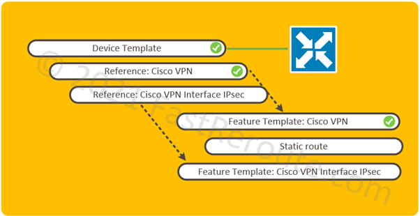
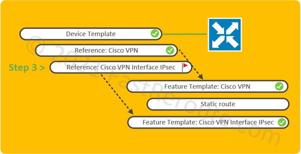
The logical elements required to be configured shown in Figure 1. All pre-configured elements have check mark symbols next to them.
In our example, the edge device has a device template attached with basic configuration applied, such as system and transport interfaces, sufficient for the router to have control connections to the controllers.
The device template uses a service VPN, which is described by the Cisco VPN feature template. This type of template, despite its name, is not related to IPsec VPN settings. Cisco VPN feature template defines VRF settings and is a container for routing and participating interface information. In our example, the user-facing interface is assumed to be configured and associated with the VRF.
While it is possible to configure all child templates from within the device template, in our example, we will pre-configure child feature templates first and then select them in the device template.
Create and Configure Cisco VPN Interface IPsec Feature Template
The first two steps deal with configuration of IPsec feature template.
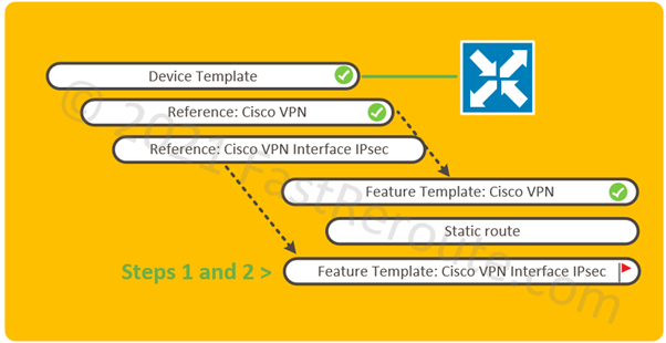
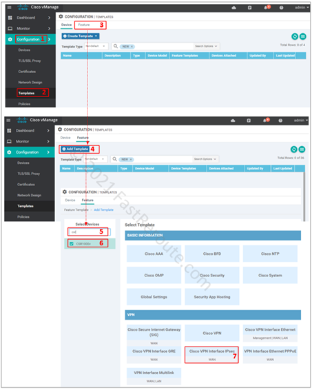
Step 1. Create feature template
- Select Configuration section of the side menu
- Click on Templates
- Click on the Feature tab
- Click on Add Template button
- Select model of devices that this feature template will be applied
- Select Cisco VPN Interface IPsec
Step 2. Configure feature template
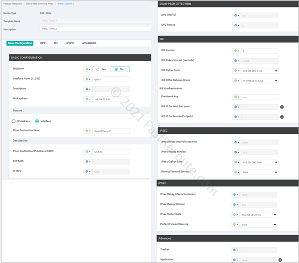
Customize IPSec tunnel parameters. There are 5 sections in IPsec template:
- Basic configuration, such as name and IP address of the tunnel interface and its underlying source (local router) and destination (remote router)
- Dead-peer detection settings
- IKE or Phase 1 parameters
- IPSEC or Phase 2 parameters
- Advanced Settings
SD-WAN requires an IP-numbered interface (/30) and supports route-based tunnels known as VTI (Virtual Template Interface) in Cisco IOS documentation.
Instead of specifying interesting traffic using ACL known as policy-based tunnels, route-based tunnels use static or dynamic routing over a tunnel interface.
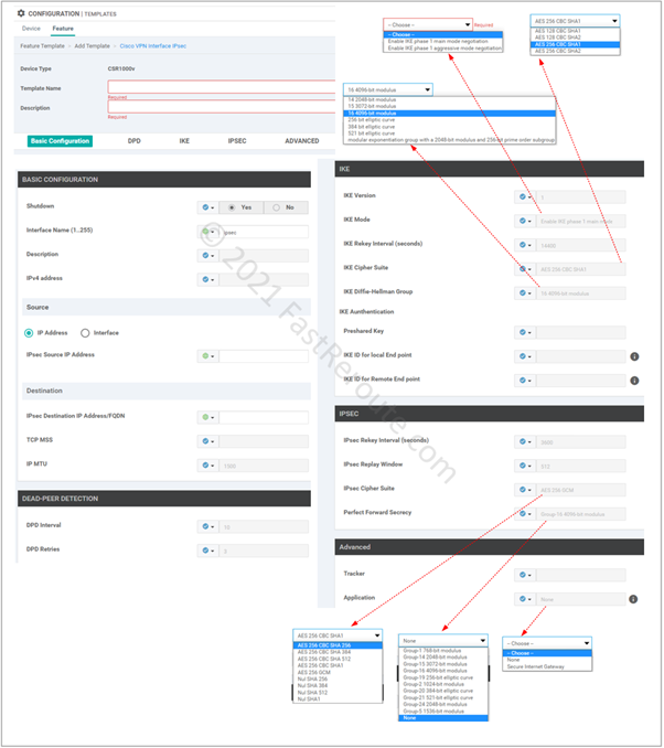
As figure 4 shows, there are various options available for both IKE and IPSEC security parameters. These need to match between tunnel endpoints.
Adjust device template to use IPsec Feature Template
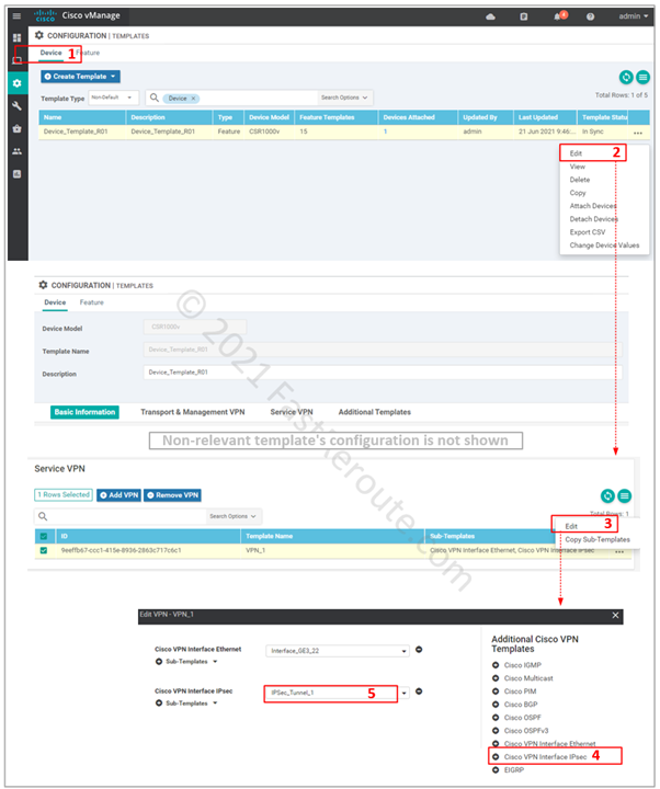
Step 3. Add feature template to the device template.
IPsec interface template can now be attached to the service VPNs. Figure 6 shows how to modify the existing device template.
Routing Configuration
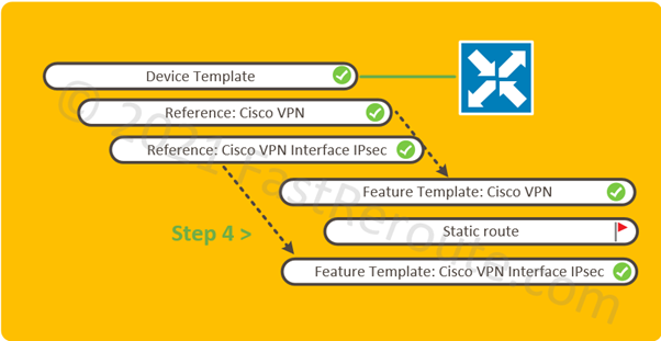
Step 4. Set-up routing over the tunnel. This can be static or dynamic-routing protocol-based. In the screenshot below, the static route configuration is shown.
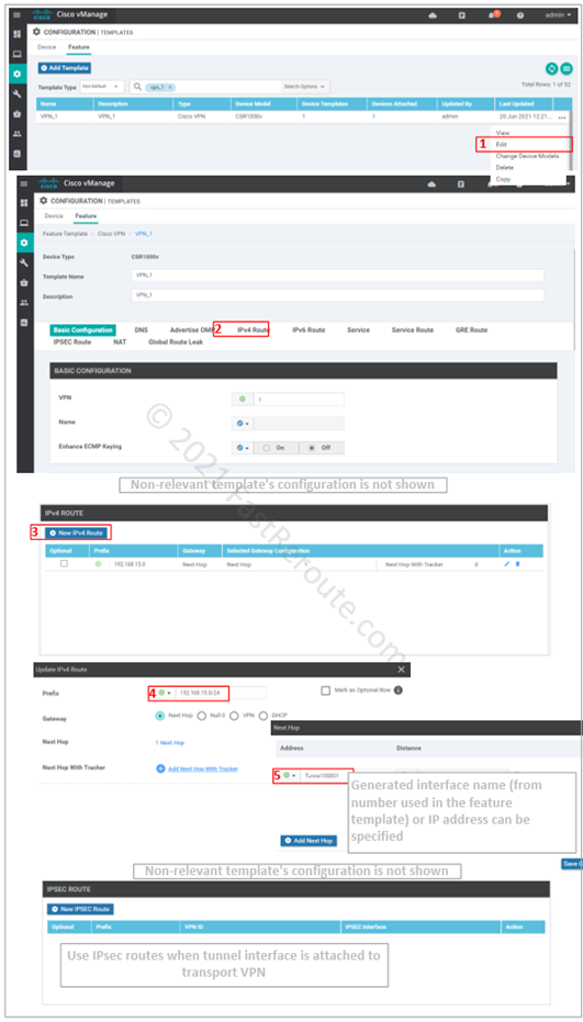
Step 5. Test the tunnel.
As the tunnels are VTI-based and have Layer 3 addresses on both sides, the simplest test is to ping the remote side of the tunnel.
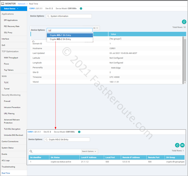
There is limited information available via real-time monitoring using vManage web interface. Native SD-WAN tunnels are also IPSec-based. These tunnels have centralized authentication and key management done by OMP instead of IKE/ISAKMP protocols used in non-SD-WAN tunnels. Real-time device options that contain string IKE in their name will be relevant to us in the context of this article.
Using SSH connection to the router these 2 commands can be used to check operational details of the tunnel:
show crypto isakmp sa/show crypto ikev2 sashow crypto ipsec sa
We will demonstrate output of these commands in the practical example below.
Cisco SD-WAN IPSec Tunnels Example
Now it’s time for a practical example. We will establish an IPsec tunnel to a Cisco IOS-XE router configured to match VPN gateways settings in public clouds. For example, AWS provides sample configuration files for different platforms (see this URL). We will apply configuration from the Cisco IOS sample, and we can assume that if our router can work with it, it will work with a real AWS gateway. The configuration is slightly adjusted to use IKEv2 by replacing all isakmp commands with IKEv2-variants.
External router configuration
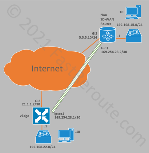
Non SD-WAN router shown on the top in figure 10 has the following configuration:
interface GigabitEthernet2
 ip address 5.5.5.10 255.255.255.0
ip route 0.0.0.0 0.0.0.0 5.5.5.1
crypto ikev2 keyring KEYRING-1
 peer 21.1.1.2
  address 21.1.1.2
  pre-shared-key cisco
crypto ikev2 proposal IKE-PROPOSAL-1
 encryption aes-cbc-256
 integrity sha1
 group 16
crypto ikev2 policy IKE-POLICY-1
 match address local 5.5.5.10
 proposal IKE-PROPOSAL-1
crypto ikev2 profile IKE-PROFILE-1
 match address local interface GigabitEthernet2
 match identity remote address 21.1.1.2 255.255.255.255
 authentication remote pre-share
 authentication local pre-share
 keyring local KEYRING-1
crypto ipsec transform-set TRANSFORM-SET esp-256-aes esp-sha-hmac
 mode tunnel
crypto ipsec profile IPSEC-PROFILE-1
 set security-association lifetime kilobytes 102400000
 set transform-set TRANSFORM-SET
 set ikev2-profile IKE-PROFILE-1
interface Tunnel0
 ip address 169.254.23.2 255.255.255.252
 ip tcp adjust-mss 1400
 tunnel source GigabitEthernet2
 tunnel mode ipsec ipv4
 tunnel destination 21.1.1.2
 tunnel protection ipsec profile IPSEC-PROFILE-1
ip route 192.168.22.0 255.255.255.0 Tunnel0
SD-WAN configuration
We followed the same steps described in the first part of the article to configure vManage. To make it easier to follow, the majority of parameters are hardcoded into the template. In a real deployment, per-device variables can be used to allow for template re-use.
Then the feature template was added to the device template under VPN 1 section (see Figure 6 above) and route to 192.168.15.0/24 was added to VPN 1 feature template (see Figure 8).
Testing and Validation
Let’s assume that we have access only to the SD-WAN router, and testing will be done only from one side of the connection. We will use the router’s command-line interface via SSH from the vManage web console, as it gives access to information not available via the web interface.
The first test that we perform is checking if the remote side of the tunnel is reachable. The “vrf 1” parameter makes sure that the router uses the correct interface.
CSR01#ping vrf 1 169.254.23.2
 Type escape sequence to abort.
 Sending 5, 100-byte ICMP Echos to 169.254.23.2, timeout is 2 seconds:
 !!!!!
 Success rate is 100 percent (5/5), round-trip min/avg/max = 1/1/1 ms
 CSR01#
If ping responses are not received, we can run “show crypto ikev2 sa” and “show crypto ipsec sa” commands. The first command displays if the IKEv2 security association is established, which is a prerequisite for IPSEC security associations. The troubleshooting should start here. If IKEv1 is used, the command is “show crypto isakmp sa.”
CSR01#show crypto ikev2 sa
  IPv4 Crypto IKEv2  SA
 Tunnel-id Local                 Remote                fvrf/ivrf            Status
 1         21.1.1.2/500          5.5.5.10/500          none/1               READY
       Encr: AES-CBC, keysize: 256, PRF: SHA1, Hash: SHA96, DH Grp:16, Auth sign: PSK, Auth verify: PSK
       Life/Active Time: 86400/545 sec
 IPv6 Crypto IKEv2  SA
We were running ping of the tunnel interface in our example, which is directly connected to both routers. This test might be successful; however, the connectivity between devices behind the tunnel gateways may still not work.
In this case, we can use the “show crypto ipsec sa” command. It displays a set of counters for the number of encrypted and decrypted packets.
If the encrypted packets count is not increasing, that usually suggests a local routing problem when traffic is not being sent out of the tunnel interface.
If the encrypted packets count does increase but decrypted doesn’t, it can mean that the remote router has routing misconfiguration.
CSR01#show crypto ipsec sa
 interface: Tunnel100001
     Crypto map tag: Tunnel100001-head-0, local addr 21.1.1.2
 protected vrf: 1
    local  ident (addr/mask/prot/port): (0.0.0.0/0.0.0.0/0/0)
    remote ident (addr/mask/prot/port): (0.0.0.0/0.0.0.0/0/0)
    current_peer 5.5.5.10 port 500
      PERMIT, flags={origin_is_acl,}
     #pkts encaps: 5, #pkts encrypt: 5, #pkts digest: 5
     #pkts decaps: 5, #pkts decrypt: 5, #pkts verify: 5
     #pkts compressed: 0, #pkts decompressed: 0
     #pkts not compressed: 0, #pkts compr. failed: 0
     #pkts not decompressed: 0, #pkts decompress failed: 0
     #send errors 0, #recv errors 0
 <output truncated>
There are some useful debug commands available, such as “debug crypto ikev2”. It can generate extensive output on a router with multiple tunnels, so be careful not to overload the production router. In the example below, we’ve changed the key on the other side of the tunnel to break the tunnel. Auth exchange failed message is logged, suggesting that we have mismatched keys and “show crypto ikev2” will not display any tunnels.
CSR01#debug crypto ikev2
 Payload contents:
  VID IDi AUTH SA TSi TSr NOTIFY(INITIAL_CONTACT) NOTIFY(SET_WINDOW_SIZE) NOTIFY(ESP_TFC_NO_SUPPORT) NOTIFY(NON_FIRST_FRAGS)
 *Jul 10 00:46:36.630: IKEv2:(SESSION ID = 2,SA ID = 1):Sending Packet [To 5.5.5.10:500/From 21.1.1.2:500/VRF i0:f0]
 Initiator SPI : EE7E2D729412F370 - Responder SPI : B37D8CA8BAB8C150 Message id: 1
 IKEv2 IKE_AUTH Exchange REQUEST
 Payload contents:
  ENCR
 *Jul 10 00:46:36.633: IKEv2:(SESSION ID = 2,SA ID = 1):Received Packet [From 5.5.5.10:500/To 21.1.1.2:500/VRF i0:f0]
 Initiator SPI : EE7E2D729412F370 - Responder SPI : B37D8CA8BAB8C150 Message id: 1
 IKEv2 IKE_AUTH Exchange RESPONSE
 Payload contents:
  NOTIFY(AUTHENTICATION_FAILED)
 *Jul 10 00:46:36.633: IKEv2:(SESSION ID = 2,SA ID = 1):Process auth response notify
 *Jul 10 00:46:36.633: IKEv2-ERROR:(SESSION ID = 2,SA ID = 1):
 *Jul 10 00:46:36.633: IKEv2:(SESSION ID = 2,SA ID = 1):Auth exchange failed
 *Jul 10 00:46:36.633: IKEv2-ERROR:(SESSION ID = 2,SA ID = 1):: Auth exchange failed
 *Jul 10 00:46:36.633: IKEv2:(SESSION ID = 2,SA ID = 1):Abort exchange
 *Jul 10 00:46:36.633: IKEv2:(SESSION ID = 2,SA ID = 1):Deleting SA
 CSR01# show crypto ikev2 sa
 CSR01#
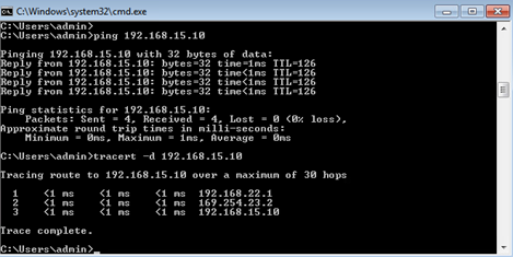
And finally we can perform end to end test from the test machines using ping and tracert commands.