In this blog post we will explore Cisco ACI fabric components and provide high-level overview of important Cisco ACI Concepts. We will not be looking into configuration workflows, which will be a topic for another post.
ACI (Application Centric Infrastructure) is a multi-tenant data center switching solution based on intent-based approach.
What is intent-based networking and how it is different from traditional software-defined networking?
Cisco defines intent-based networking as 3 processes:
- Translation, or converting business requirements into policies
- Activation, or transforming a policy into specific configuration applied to a device
- Assurance, or ensuring that the intent has been realized
Traditional software-defined networking focuses on activation, i.e. orchestration and configuration automation. See Cisco Viptela SD-WAN post to read about Cisco SDN approach for WAN.
Cisco products implement all 3 processes. ACI is responsible for translation and activation. Cisco Tetration and Network Assurance Engine are responsible for assurance aspect.
What are the benefits of implementing Cisco ACI in the data center?
ACI fabric is centrally managed via single Web-based management interface. ACI also provides extensive Application Programming Interface (API), so it can be fully automated.
ACI has multi-tenant design out of the box. It ensures that tenants are separated not only on data plane, but also by providing tenant-specific management capability.
Cisco ACI is easy to deploy, as user doesn’t need to understand or configure fabric protocols, such as VXLAN, underlay routing protocols or multicast routing. Provisioning of new leaf switches or replacing existing ones is very simple from discovery to applying template-based configuration.
There are some new concepts and configuration patterns to master, as ACI is rather different from the way traditional switches are configured and operated. However, ACI brings many benefits with centralized configuration based on templates and policies. For example, consistency across many devices is easily achieved and known working settings can be re-used when new device or tenant is introduced.
Cisco ACI Components
2 main components of ACI are:
- Switching Fabric
- Controllers
ACI Switching Fabric
Switching fabric is based on leaf-and-spine topology. Each leaf connects to every spine with no direct connections between leafs or spines. Servers, routers for external connectivity, firewalls and other network devices connect to leaf switches only.
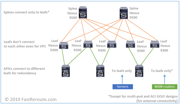
With two layers there is always a single hop between any pairs of leaf switches – spine switch layer. Throughput can be horizontally scaled by introducing additional spine switches. The inter-switch connections are point-to-point layer-3 links. Therefore, all links can be evenly utilized with Equal-Cost Multi Pathing (ECMP). Switch fabric utilizes VXLAN encapsulation or MAC in UDP with Cisco proprietary extensions. Data plane operation will be explained in the next section in more detail.
Cisco ACI switch portfolio consists of modular Nexus 9500 and fixed Nexus 9300 families of switches. Not all switches in these families can run in ACI mode. Some of the switches are NX-OS mode only and some of them can run in both modes.
ACI Spine Switches
Important: Always check Cisco website for the latest updates and compatibility information.
| Switch model | Description | ACI spine/NX-OS |
|---|---|---|
| X9736PQ line card (reached end of sale) | 36 x 40G QSFP+ | ACI Spine |
| X9732C-EX line card | 32 x 100G QSFP28 | Both |
| X9732C-FX line card (on roadmap) | 32 x 100G QSFP28 | Both |
| X9736C-FX line card | 36 x 100G QSFP28 | Both |
| X9336PQ switch (reached end of sale) | 36 x 40G QSFP+ | ACI Spine |
| 9332C switch | 32 x 40/100G QSFP28 | Both |
| 9364C switch | 64 x 40/100G QSFP28 | Both |
| 9316D-GX switch | 16 x 400/100G QSFP-DD | Both |
| 93600CD-GX switch (on roadmap) | 28 x 40/100G QSFP28 and 8 x 400/100G QSFP-DD | Both |
Table 1. Cisco ACI Spine Switches
Nexus 9500 family has 3 models of chassis with 4-, 8- and 16- slots for line cards. Each of the models accepts a single or pair of supervisor cards, set of fabric modules and line cards. Fabric modules and line cards is what provides ability of the chassis to run in ACI mode. Currently there are 3 families of line cards:
- Cisco and merchant ASICs based. Only single line card X9736PQ supports ACI spine functionality in this family and is compatible with C9504-FM, C9508-FM and C9516-FM fabric modules.
- R-Series (Deep Buffer). This family doesn’t provide ACI support and model of its line cards name starts with X96xx.
- Cloud Scale ASICs based. This more recent family of modules contains ACI spine capable X9732C-EX, X9732C-FX (roadmap as of Sep 2019), X9736C-FX line cards and C9504-FM-E, C9508-FM-E, C9508-FM-E2 and C9516-FM-E2 fabric modules
Fixed Nexus 9300 switches that can also be spine switches are as per list below:
- 9332C
- 9364C
- 9316D-GX
- 93600CD-GX (roadmap as of Sep 2019)
All of the switches in this list are Cloud Scale based.
ACI Leaf Switches
Leaf switches are all part of Nexus 9300 family on Cloud Scale technology with the exception of 93120TX. The table below shows available options for ACI leafs.
| Switch model | Description | ACI leaf/NX-OS |
|---|---|---|
| 93120TX | 96 x 100M/1/10GBASE-T and 6 x 40G QSFP+ | Both |
| 93108TC-EX | 48 x 10GBASE-T and 6 x 40/100-G QSFP28 | Both |
| 93180YC-EX | 48 x 10/25G and 6 x 40/100G QSFP28 | Both |
| 93180LC-EX | Up to 32 x 40/50G QSFP+ or 18 x 100G QSFP28 | Both |
| 9348GC-FXP | 48 x 100M/1GBASE-T, 4 x 10/25G SFP28 and 2 x 40/100G QSFP28 | Both |
| 93108TC-FX | 48 x 100M/1/10GBASE-T and 6 x 40/100G QSFP28 | Both |
| 93180YC-FX | 48 x 1/10/25G fiber ports and 6 x 40/100G QSFP28 | Both |
| 9336C-FX2 | 36 x 40/100G QSFP28 | Both |
| 93216TC-FX2 | 96 x 100M/1/10GBASE-T and 12 x 40/100G QSFP28 | Both |
| 93240YC-FX2 | 48 x 1/10/25G fiber ports and 12 x 40/100G QSFP28 | Both |
| 93360YC-FX2 | 96 x 1/10/25G fiber ports and 12 x 40/100G QSFP28 | Both |
| 9316D-GX (on roadmap) | 16 x 400/100G QSFP-DD | Both |
| 93600CD-GX | 28 x 40/100G QSFP28 and 8 x 400/100G QSFP-DD | Both |
Table 2. Cisco ACI Leaf Switches
APIC Controllers
The core of ACI deployment is Cisco Application Policy Infrastructure Controller, or APIC. It is central point for ACI fabric configuration and monitoring.
APIC is a physical appliance based on Cisco UCS C-series server. ACI deployment requires at least 3 APIC controllers forming APIC cluster. The maximum number of APIC controllers in cluster is 5.
For fabric management, each APIC is physically connected to 2 different leaf switches, with one of the interfaces as active and the second one as standby. In addition to these 2 links, out-band connections for CIMC and appliance are required.
Virtual APIC controller can be launched on VMWare ESXi hypervisor and is component of Cisco Mini ACI fabric for small scale deployments. In Cisco Mini ACI fabric only single physical APIC is required, while second and third can be virtualized.
There are 2 APIC configurations currently available – medium and large (more than 1200 edge ports). Appliance must be ordered using published part number and not as C-series server with matching parameters. The configuration details for each the options are shown in the Table 3.
| Configuration | Medium | Large |
|---|---|---|
| Part number | APIC-M3 | APIC-L3 |
| CPU | 2 x 1.7 GHz Xeon Scalable 3106/85W 8C/11MB Cache/DDR4 2133M | 2 x 2.1 GHz Xeon Scalable 4110/85W 8C/11MB Cache/DDR4 2400MHz |
| RAM | 6 x 16GB DDR4-2666-MHz RDIMM/PC4-21300 | 12 x 16GB DDR4-2666-MHz RDIMM/PC4-21300 |
| HDD | 2 x 1 TB 12G SAS 7.2K RPM SFF HDD | 2 x 2.4 TB 12G SAS 10K RPM SFF HDD |
| CNA | Cisco UCS VIC 1455 Quad Port 10/25G SFP28 CNA PCIE | Cisco UCS VIC 1455 Quad Port 10/25G SFP28 CNA PCIE |
Table 3. Cisco APIC Controllers
ACI Fabric Operation
ACI Fabric Forwarding Overview
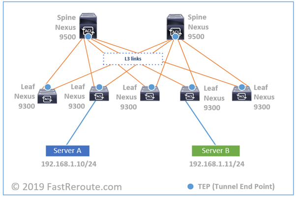
Let’s consider the example topology in the diagram below. Orange links between leafs and spines are Layer 3. Therefore, no Layer 2 loops can occur and no Spanning Tree Protocol is required. These links form underlay network. All data traffic traversing over them is VXLAN-encapsulated.
If you capture a packet on any of those links, it will be UDP-encapsulated traffic between loopback interfaces of leaf switches. This IP address is called TEP for Tunnel End Point. In some scenarios, the destination IP address can be multicast or spine switches loopbacks as well.
This UDP traffic is encapsulated payload of Layer 2 traffic received on downstream interface. Let’s start with Server A sending IP packet to Server B and to simplify our example, let’s assume it already knowns MAC address of Server B. Server A will create unicast IP packet, pack it into Ethernet frame and send it to the switch.
The switch will try to resolve the destination leaf’s TEP IP address. There are several mechanisms available, but let’s assume it knows that it is connected to leaf switch #4. It will take Ethernet frame and pack it into new UDP VXLAN datagram, with new IP header with the source IP as leaf switch #2’s VTEP IP and destination as leaf switch #4’s VTEP IP. Encapsulated traffic will be load-balanced via 2 available spines.
Underlay Protocols
In ACI terminology, underlay or set of orange links in the diagram above is called Infra VRF. The IP addresses in underlay are isolated and not exposed to tenants. In contrast, the data traffic between servers and clients is transferred in overlay networks. It is similar to how VPNs are built over Internet or Layer 3 VPNs over MPLS network.
The orange links in the Figure 2 run link-state routing protocol – IS-IS. It’s main purpose is to provide reachability between Tunnel End Points (TEPs). It is similar to how VXLAN network is built on Nexus switches using NX-OS, which can run OSPF as routing protocol instead.
Different to VXLAN EVPN setup, ACI doesn’t run EVPN with BGP to distribute endpoint reachability information. Instead, COOP (Council of Oracle Protocol) is responsible for endpoint information tracking and resolution. MP-BGP, however, is still used to propagate routing information that is external to fabric.
Cisco ACI Basic Concepts
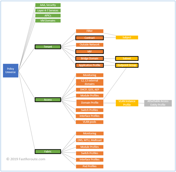
Cisco introduced many new terms with ACI. All configuration constructs and their interaction is documented in ACI policy model. Each construct is represented by a Managed Object (MO), which form hierarchical Management Information Tree (MIT).
Figure 3 displays partial view of the MIT. Policy Universe on the left is root. Solid lines represent containment and dotted lines – association. For example, Tenant class contains one or more Bridge Domain instances and a Bridge Domain is associated with a VRF.
As this post is introductory, we will review some of the terms relevant in context of how fabric works. There are also important terms around how fabric is being configured, however, this will be cover in another post.
Tenants
Tenant is a logical grouping of various policies. It can be a customer or a department within your organization. By creating different tenants you provide ability to delegate management of tenant-specific settings.
There are 3 built-in tenants: Infra, Common and Management. Infra tenant is responsible for fabric underlay, Common tenant hosts resources that are shared between other tenants and Management tenant is for in-band and out-of-band configuration.
VRFs
Virtual Routing and Forwarding instance or VRF has the same meaning as in traditional network, it is a Layer 3 routing domain. The isolation is achieved by keeping routing information separate.
For example, 2 different VRFs can both have 192.168.0.0/24 network defined in the same way if both had dedicated non-connected physical networks and routers. By default, VRFs cannot communicate to each other.
You can export or leak some of the routes between VRFs, but in this case you need to ensure that the network don’t have overlapping subnets.
A tenant can have a single or multiple VRFs.
Bridge Domains and Subnets
Bridge domain is a Layer 2 flood domain. A VLAN in traditional network is a Layer 2 flood domain. You might be wondering, why not to keep the same term. One of the reasons, is that fabric uses VXLAN IDs to differentiate Layer 2 networks between each other. VLAN IDs can be re-used and even overlap between different ports in recent versions of ACI software, so they cannot be used as fabric-wide identifiers for a specific Layer 2 domain.
Bridge domain requires association with VRF and can contain one or more subnets. It is possible to assign multiple subnets to a single bridge domain (analogy is a secondary address on SVI) or one to one relationship between bridge domain and subnet can be established.
Adding a subnet to bridge domain and enabling unicast routing creates routed interface or SVI in that subnet. In ACI all leafs are using the same SVI’s IP address for use as default gateway for the subnet. This functionality is called pervasive gateway (or anycast gateway) and optimize Layer 3 processing efficiency, as routing is distributed across all leafs without need to have a central device to perform routing.
Application Profiles and EPGs
Application Profiles are containers for Endpoint Groups. EPG is a logical group of endpoints and one of the main components of ACI policy model. Endpoints include physical servers, virtual machines and other network-connected devices.
EPG membership can be statically configured, for example, to be based on a specific port and VLAN on it. Or it can be based on VM’s NIC port group membership via dynamic negotiation with Virtual Machine Manager.
The policies in ACI are applied to EPGs and, by default, each EPG is isolated from other EPGs.
Contracts
If one EPG A needs to access services provided by EPG B, then EPG A is called consumer and EPG B is called provider. Default behavior in ACI is to block all inter-EPG traffic. Contract must be defined to facilitate this communication.
Contract consists of subjects which in turn contain list of filters. Filters are similar to access-lists and contain entries which match the traffic.
Contracts are directional and differentiate between traffic going from consumer to provider and traffic in reverse direction.
Access Policies
Access policies control configuration of interfaces connecting to physical servers, routers and hypervisors. Objects living under Access Policies include:
- Pools of IDs, or grouping of VLANs, VXLAN IDs and multicast addresses
- Domains and their types define how devices are connected to leaf switches, for example, physical domain is used for bare metal servers and VMM domain is used for integration with hypervisors
- Interface Policies, Policy Groups and Profiles. Policy controls specific setting of an interface, which are grouped together to be used in profile along with interface selector
- Switch Policies, Policy Groups and Profiles. These objects control switch-level configuration and by associating Interface Profiles with Switch Profiles, interface settings can be applied to the specific leaf switch
Fabric Policies
Fabric policies and objects under it control internal fabric interface and protocols configuration. For example, parameters such as Fabric MTU is defined by Global Fabric policy and SNMP, date and time parameters are specified by Pod Profiles.